I. Abbreviations:
AMBA: Advanced Microcontroller Bus Architecture
ADK: AMBA Design Suite
AHB: Advanced High Performance Bus
AHB-AP: AHB access port
APB: Advanced Peripheral Bus
ARM ARM: ARM Architecture Reference Manual
ASIC: Industry-specific ASIC
ATB: Advanced Tracking Bus
BE8: Byte invariant big endian mode
CPI: number of cycles per instruction
DAP: Debug access port
DSP: Digital Signal Processing (Device)
DWT: data observation point and tracking
ETM: Embedded Trace Macrocell
FPB: Flash address overloading and breakpoints
FSR: fault status register
HTM: Core Sight AHB Trace Macro Unit
ICE: In-Circuit Emulator
IDE: Integrated Development Environment
IRQ: Interrupt request (usually an external interrupt request)
ISA: Command System Architecture
ISR: Interrupt Service Routine
ITM: Instrumented Trace Macrocell
JTAG: Connection Point Test Action Group (a standard for testing and debugging interfaces)
LR: connection register
LSB: least significant bit
MSB: Most significant bit
LSU: load storage unit
MCU: Microcontroller Unit
MPU: Memory Protection Unit
MMU: Memory Management Unit
MSP: main stack pointer
NMI: Non-maskable interrupt
NVIC: Nested Vectored Interrupt Controller
PC: Program Counter
PPB: Private peripheral bus
At the same time, it is also required to:
2. Value:
1. 4''hC , 0x123 all represent hexadecimal numbers
2. #3 indicates the number 3 (eg, IRQ #3 means the number 3 interrupt)
3. #immed_12 represents a 12-bit immediate
4. Register bits. Usually a value that represents a bit segment, for example
Bit[15:12] indicates the number of the bit number from 15 down to 12, the value of this segment.
Three. Register access type
1. R means read only
2. W means write only
3. RW means readable and writable (the first 3 seem to be known to everyone on earth)
4. R/Wc means readable, but write access will clear it to 0.
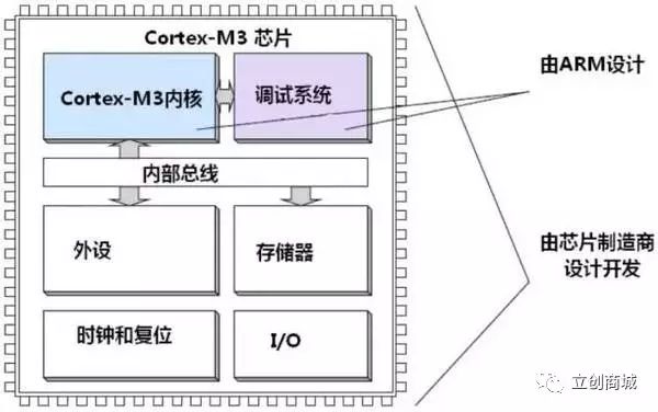
Introduction to Cortex-M3 chip
1. The basic structure of the chip is as follows:
2, ARMv7 knowledge
In this version, the kernel architecture changed from a single style to three styles for the first time:
Style A: Designed for high performance "open application platforms" - getting closer to the computer.
Style R: For high-end embedded systems, especially those with real-time requirements - fast and real-time.
Style M: ​​For deep embedded, single-chip style systems.
Introduction:
A: An "open application platform" for high performance, for processors that need to run complex applications. Support for large embedded operating systems.
R: For high-end embedded systems, requiring real-time.
M: For deep embedded, microcontroller-style systems.
3. The stage of the Cortex-M3 processor
High performance + high code density + small silicon area makes CM3 an ideal processing platform for large areas, mainly used in the following fields:
(1) Low-cost single-chip microcomputer
(2) Automotive Electronics
(3) Data communication
(4) Industrial control
(5) Consumer electronics
4. Overview of Cortex-M3
(1 Introduction
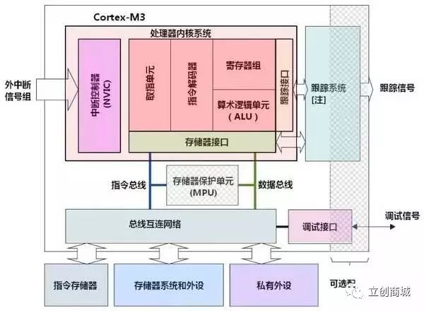
The Cortex-M3 is a 32-bit processor core. The internal data path is 32 bits, the registers are 32 bits, and the memory interface is also 32 bits. The CM3 uses a Harvard architecture with an independent instruction bus and data bus that allows the fetch and data access to be parallel. As a result, data access no longer occupies the instruction bus, which improves performance. To achieve this feature, CM3 contains several bus interfaces internally, each optimized for its own application, and they can work in parallel. But on the other hand, the instruction bus and the data bus share the same memory space (a unified memory system).
More complex applications may require more storage system functionality, for which the CM3 provides an optional MPU and an external cache can be used if needed. In addition, in CM3, Both Little Endian mode and Big Endian mode are supported.
(2) Simplified diagram of Cortex-M3
(3) Register set
The processor has a register set of R0-R15, where R13 is the stack pointer SP, SP has two, but only one can be seen at the same time, this is the so-called "banked" register.
  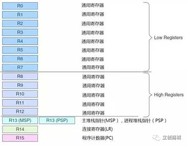
a, R0-R12 are 32-bit general-purpose registers for data operations. Note, however, that most 16-bit Thumb instructions can only access R0-R7, while 32-bit Thumb-2 instructions can access all registers.
b. Cortex-M3 has two stack pointers, however they are banked, so only one of them can be used at any one time.
Main Stack Pointer (MSP): The default stack pointer used after reset for the operating system kernel and exception handling routines (including interrupt service routines)
Process Stack Pointer (PSP): Used by the user's application code.
The lowest two bits of the stack pointer are always 0, which means that the stack is always 4-byte aligned.
c, R14: connection register - when calling a subroutine, R14 stores the return address
d, R15: program count register - point to the current program address, if you modify its value, you can change the execution flow of the program (there are many advanced techniques here)
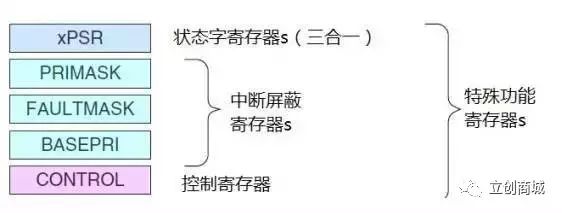
e, Cortex-M3 also carries a number of special function registers at the kernel level, including:
Program Status Word Register Set (PSRs)
Interrupt Mask Register Group (PRIMASK, FAULTMASK, BASEPRI)
Control register (CONTROL)
The Cortex-M3 processor supports two processor operating modes and also supports two levels of privileged operation.
The two modes of operation are: processor mode and thread mode. The intent of introducing two patterns is the code used to distinguish between normal application code and exception service routines -- including code that interrupts service routines.
The other side of the Cortex-M3 is the privilege hierarchy—privilege and user. This can provide a protection mechanism for memory access so that ordinary user program code cannot perform operations involving criticality accidentally or even maliciously. The processor supports two privilege levels, which is also a basic security model.
  
When CM3 runs the main application (thread mode), either privilege level or user level can be used; however, exception service routines must be executed at the privilege level. After reset, the processor enters thread mode by default, with privileged access. At the privilege level, the program can access all ranges of memory (if there is an MPU, but also outside the forbidden area specified by the MPU), and can execute all instructions.
Programs at the privilege level can do whatever they want, but they may also play in themselves - switch to the user level. Once you enter the user level, you have to go "legal procedures" when you want to come back - the user-level program can't simply rewrite the CONTROL register and go back to the privilege level. It must first "appeal": execute a system call instruction ( SVC). This triggers an SVC exception, which is then taken over by the exception service routine (usually part of the operating system). If the entry is approved, the exception service routine modifies the CONTROL register to re-enter the privilege level in user-level thread mode.
In fact, the only way from the user level to the privilege level is the exception: if an exception is triggered during program execution, the processor always switches to the privilege level and returns to the previous one when the exception service routine exits. status
  
By introducing privilege level and user level, it is possible to limit certain untrusted or undebugged programs on the hardware level, and prevent them from randomly configuring the registers involved, so that the reliability of the system is improved. Further, if it is equipped with an MPU, it can also be used as a supplement to the privilege mechanism to protect critical storage areas from being destroyed. These areas are usually areas of the operating system.
(4) Built-in nested vector interrupt controller
The Cortex-M3 is equipped with an interrupt controller, the Nested Vectored Interrupt Controller (NVIC), at the core level. It has a deep "intimate contact" with the kernel - it is tightly coupled to the kernel.
NVIC provides the following features:
  
Nested interrupt support
Vector interrupt support
Dynamic priority adjustment support
Interrupt delay is greatly reduced
Interrupt can be masked
  
Nested Interrupt Support: Nested Interrupt Support has a wide range of coverage, covering all external interrupts and most system exceptions. The external manifestation is that these exceptions can be given different priorities. The current priority is stored in a dedicated field of xPSR. When an exception occurs, the hardware automatically compares the priority of the exception to a higher priority than the current exception. If a higher priority exception is found, the processor will interrupt the current interrupt service routine (or normal program) and service the new exception - that is, immediately preempt.
  
Vector Interrupt Support: When starting to respond to an interrupt, CM3 will automatically locate a vector table, and find the ISR entry address from the table based on the interrupt number, and then jump to the past execution. There is no need for software to tell which interrupt occurred, as in the previous ARM, and there is no need for a semiconductor manufacturer to provide a proprietary interrupt controller to do this. As a result, the interrupt latency is greatly reduced.
  
(5) Memory mapping
  
Cortex-M3 supports 4G storage space, as shown in the following figure:
  
  
(6) Bus interface
  
There are several bus interfaces inside the Cortex-M3 so that the CM3 can be addressed and accessed simultaneously (accessing memory). They are:
Instruction memory bus (two)
System bus
Private peripheral bus
  
There are two code memory areas that are responsible for accessing the code memory area, the I-Code bus and the D-Code bus. The former is used for indexing and the latter is used for table lookup operations, which are optimized at the optimal execution speed.
The system bus is used to access memory and peripherals, including SRAM, on-chip peripherals, off-chip RAM, off-chip expansion devices, and part of the system-level memory area.
The private peripheral bus is responsible for accessing a portion of the private peripherals, primarily accessing the debug components. They are also in system level storage.
(7) Memory Protection Unit (MPU)
The Cortex-M3 has an optional memory protection unit. With it, you can impose different access restrictions on privileged access and user-level access. When a violated is detected, the MPU generates a fault exception that can be analyzed by the service routine of the fault exception and corrected whenever possible.
MPU has a lot of ways to play. The most common is to use the MPU by the operating system so that the data of the privileged code, including the data of the operating system itself, is not corrupted by other user programs. The MPU is managed by zone when protecting memory. It can set certain memory regions to read-only, thus avoiding accidental changes in the contents there; it is also possible to isolate data areas between different tasks in a multitasking system. In short, it will make embedded systems become more robust, more reliable (standard in many industries, especially in aviation, you have to use the provisions of the MPU to protect the exercise of functions - translation note).
(8) A brief review of the Cortex-M3
  
1, high performance
  
Many instructions are single-cycle - including multiplication-related instructions. And from the overall performance, the Cortex-M3 is comparable to most other architectures.
  
The instruction bus and the data bus are separated, and the values ​​and accesses can be paralleled.
  
The arrival of Thumb-2 bid farewell to the old generation of state switching, and no longer need to spend time switching between the 32-bit ARM state and the 16-bit Thumb state. This simplifies software development and code maintenance, making the product faster.
  
The Thumb-2 instruction set brings more flexibility to programming. Many data operations can now be done with shorter code, which means that the Cortex-M3 has a higher code density and less memory requirements.
  
The fingers are processed in 32 bits. Up to two instructions can be fetched in the same cycle, leaving more bandwidth for data transfer.
  
The Cortex-M3 is designed to allow high-frequency operation of the microcontroller (modern semiconductor manufacturing technology can guarantee speeds above 100MHz). Even at the same speed, the CM3 has a lower number of instruction cycles per cycle (CPI), so the same MHz can be used. More work; on the other hand, the same application requires a lower frequency on the CM3.
  
2, advanced interrupt processing function
  
The built-in nested vectored interrupt controller supports 240 external interrupt inputs. The vectorized interrupt function greatly reduces the interrupt latency because the software is not required to determine the source of the interrupt. The nesting of interrupts is also implemented at the hardware level and does not require software code to implement.
  
When the Cortex-M3 enters the exception service routine, it automatically pushes R0-R3, R12, LR, PSR and PC, and automatically pops them up when it returns. This is so refreshing! Both speed up the response of the interrupt and no longer need assembly language code
  
NVIC supports setting different priorities for each interrupt, making interrupt management extremely flexible. The implementation of the thickest line also supports at least level 8 priority, and can be dynamically modified.
  
There are two tricks to optimize the interrupt response. They are the "biting tail interrupt mechanism" and the "late arrival interrupt mechanism".
  
Some instructions that require more cycles to execute can be interrupted-continued—just like they are a string of instructions. These instructions include loading multiple registers (LDMs), storing multiple registers (STMs), PUSHs with multiple registers, and POPs with multiple registers.
  
Unless the system is completely locked, the NMI (non-maskable interrupt) will respond the first time the request is received. For many safety-critical applications, NMI is essential (such as an emergency shutdown when the chemical reaction is about to get out of control).
  
Through the above we can easily understand some of the basic knowledge and structure of STM32, and lay the foundation for learning STM32.
Ic Pmic,Pmic Full Half Bridge Drivers,Pmic Gate Drivers,Integrated Circuits Ics Pmic
Shenzhen Kaixuanye Technology Co., Ltd. , https://www.iconlinekxys.com