Abstract: In order to improve the anti-collision of trams and light rail vehicles, the anti-collision structure of the car body was developed and tested.
This article refers to the address: http://
Keywords: tram; light rail vehicle; collision avoidance
1 Overview
In the summer of 2004, the Safetram project to improve the safety of light rail passengers and passengers in crashes is nearing completion. The Safetram project was launched on July 1, 2001 for a three-year period, funded by the European Union and is part of the fifth framework research program.
To a certain extent, due to the Kyoto Protocol and related efforts to reduce carbon dioxide emissions and energy consumption, tram lines and light rail lines around the world are undergoing a renaissance phase. Factors contributing to the increase in tram and tram trains (known as suburban trains) include greater traffic and lower energy consumption than buses, while at the same time being less expensive and more convenient than traditional heavy-duty subways.
The energy-saving advantages of light rail include light body structure and regenerative braking, but on the contrary, it is this lightweight structure that causes problems in collision avoidance. On unisolated lines, trams must share roads with other users and often drive without a fixed signal. Both of these factors increase the risk of a collision.
The Safetram project is designed to increase the cost-effectiveness of passive safety – by ensuring a collision-resistant survival space between vehicles to reduce impact and extend the duration of the impact, thus avoiding violent impact. The main objective is to demonstrate the feasibility of controlling the collision energy and acceleration of typical tram and tram trains at acceptable cost within technical limits.
The project is based on the heavy rail anti-collision program implemented by railway operators, the rte EuramSafetran project, the experience of the automotive industry and the European Crossral project. The work is shared by 13 partners representing research institutes, manufacturers and operators, led and coordinated by the Portuguese company Bombardier Transportation.
The Safetram project began with the statistical and risk analysis of accidents and reviewed the design and manufacture of the front end of the collision-resistant body. For road accidents, the regulations on the structure of the car and the internal passive safety were also studied, and the road vehicle regulations were examined, which would affect the performance of the trams during the collision between the two types of vehicles, and emphasized the applicability of the general safety concept. .
In order to obtain the collision performance and the optimized crushing characteristics under different collision conditions, the two-dimensional multi-body dynamics model is used to simulate the overall dynamics of urban trams and suburban vehicles.
This modeling process, along with subsequent verification of the dynamics tests and results of the components and the entire vehicle body, will prepare for the development of future vehicle design standards. To achieve this goal, the project is working with the European Standardization Committee's 256 Technical Committee Working Group 2 to develop European standards for collision-resistant structural requirements.
The results of the Safetram project will form the basis for Type IV and V trams in Part 2 of the European Standardization Committee's European Standard 12663. This will greatly contribute to meeting the passive safety requirements of tram operators, and we believe that it will help to eventually eliminate operational barriers to the market for rail public transport vehicles.
2 Risk analysis
At present, the safety of trams is mostly based on dynamic factors, such as high-performance braking. In order to meet the requirements of light vehicles, the body of the urban tram can usually withstand 200kN ~ 400kN impact load without structural deformation, the suburban car body shell can withstand 600kN impact load without structural deformation, and the trunk railway The vehicle can withstand at least 1500kN of impact load without structural deformation.
However, tram accidents have been frequent, causing injuries to passengers, passengers, pedestrians, car drivers and other road users. In the past 10 years, only 6 operators in Europe reported 19,000 accidents, resulting in 3,050 casualties.
Two different sources are used to assess risk, and the product of the frequency of a given type of incident and the severity of its consequences is defined as the risk of injury. For urban trams, an accident database of the existing road network is used. Since there is no comparable database for the tram train project, the statistics of the regional train operation accidents of the German Federal Railways DB) and the French National Railway (NCF) are used.
After assessing the tram accidents in the countries where the project partners are located and in Belgium, it quickly shows that for passengers and passengers, the greatest danger comes from violent emergency braking, rather than the actual phase of another vehicle. hit. The analysis determined that a low-floor tram and a truck collided, resulting in a 10-9 injury per passenger kilometer, while the risk of injury from emergency braking was 10-7.
In order to alleviate the severity of injuries to tram drivers and passengers, the project partners believe that it is important to improve the passive safety of vehicles. The design of the anti-collision vehicle requires it to be crushed in a controlled, progressive manner to ensure that the loss of surviving space in the driver and passenger area is minimized. By controlling the collision energy and redesigning the internal structure of the tram, the safety of passengers and passengers can be improved. By ensuring progressive crush deformation, the deceleration can be controlled and limited to an acceptable level.
In the next phase of the project, four collision scenarios were set for each of the two main models:
C1: Emergency braking of urban trams (.73m/s);
C2: The same city trams collide at a speed of 20km/h;
C3: The urban tram crashes at a speed of 25km/h with a light-duty truck that is parked at a 45o angle to the track;
C4: Urban trams collide with a suburban car at a speed of 10km/h;
P1: Suburban vehicles collide with an 80t railway vehicle equipped with side buffers at a speed of 25km/h;
P2: The suburban car collided with an anti-collision train with a weight of 129t at a speed of 22km/h;
P3: The same suburban vehicles collide at a speed of 36km/h;
P4: The suburban car collided with a rigid 16.5t heavy truck on the level crossing at a speed of 40km/h.
In the P2 collision scenario, the anti-collision train refers to a train with modern force-displacement characteristics at the front end.
In order to obtain the crash performance and target-optimized crush characteristics in different scenarios, a two-dimensional multi-body dynamics model was used to simulate the overall dynamic performance of the vehicle.
3 Design and test
Based on the initial research, the afetran project team created two new design concepts for urban and suburban trams. In order to test different materials, it was decided to use aluminum to make the urban tram body (Fig. 1) and use steel to make the suburban car body (Fig. 2).
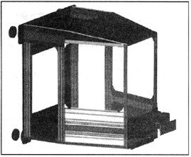
Fig.1 Design of aluminum driver cab module for anti-collision urban tram
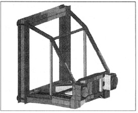
Figure 2 Design of the steel cab for the suburban car
In order to simplify the application of the anti-collision principle, a lot of emphasis is placed on modularity. For example, the cab is designed as an integral module with a clear mechanical interface and the deformation unit is designed as a separate module. The reliability of replaceable components used to absorb energy in a collision will increase and reduce the maintenance and life cycle costs of trams and light rail vehicles.
The urban tram design specifies two energy absorption stages. The first stage that can be reused uses a hydraulic damper that absorbs 35kJ of energy. The second stage, which is not reusable, uses a crushable aluminum extrusion that absorbs up to 100kJ. The maximum total displacement is about 500mm.
The energy absorption of suburban car collisions is divided into four stages. The first stage buffer also absorbs energy of 35 kJ. Other stages are not reusable. The side buffer absorbs energy of 160 kJ and the central aluminum honeycomb structure further absorbs energy by 64 kJ. Both units are designed as replaceable modules. In the final stage, energy is absorbed through a crushing zone at the front end of the car body structure, and the maximum absorbable energy is 600 kJ. The maximum displacement in this case is 700 mm.
Of course, in any given collision, the actual absorbed energy will depend on the particular collision scenario, since the roles of the individual energy absorption units are different.
In addition to shortening the design process of the special type of car body and increasing manufacturing productivity, the module design method also has important advantages in certification. The module's crash performance can be evaluated during the component test phase.
4 actual verification
In order to verify multi-body dynamics and finite element calculations, a physical collision test was carried out at the Nigrudud Test Center in Poland in November 003 (Fig. 3, Fig. 4, Fig. 5), and in the UK Automotive Manufacturing Research Association. The taxi test was conducted at the (MIRA) laboratory. The purpose is to verify the calculations by representative practical tests, for which collision scenarios C2 and P1 are selected. Scenario C2 was simplified to a single vehicle with an experimental cab installed at its end striking a rigid wall at a speed of 14 km/h.
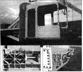
Figure 3 Physical collision test of the driver module of the urban tram
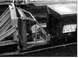
Figure 4 Collision test of the cab driver cab module
The results of the urban tram test are consistent with the expected performance during the calculation phase. There is a slight difference in the deformation of the suburban car, which is explained by a further understanding of the test conditions.
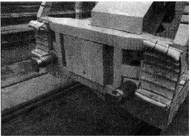
Figure 5 The deformable side and central energy absorbing unit is mounted on a suburban vehicle as the second line of defense behind the hydraulic shock absorber
5 interior layout
In order to improve the survival possibilities of the passengers and passengers of the vehicle, it is important to limit the level of acceleration felt by the passengers and the equipment inside the vehicle. In this case, standing passengers are the most vulnerable.
At present, the interior layout of the tram shows that there are many defects in the design of the passenger compartment, which poses a serious security threat to the passengers in the accident. The Safetram project reviewed various interior layouts and will present a set of safety improvement recommendations in its final report that will be evaluated by establishing dynamic models and taxi tests.
Preventing damage in secondary collisions requires consideration of the interior layout and the human response to impact and acceleration. The biomechanics of standing passengers is a new and challenging area of ​​research.
The final phase of the Safetram project was a series of gliding tests using a hybrid human body II model. These tests were carried out by the French National Railway in INRETS in August 2003 and by the British MIRA laboratory in December 2003. The kinetic model is used to calculate the behavior and response of the seated passenger and driver to determine the damage that occurs in the specified collision scenario.
For lithium iron phosphate(LiFePO4) power battery system with brand of Taihang Jiaxin, it has the advantages of long cycle life, high rate of discharge performance, good safety, available for the requirement for Fast Charging and so on.
Using self-developed Battery Management System (BMS) which has the functions of advanced battery self-management, communication, alarm and other functions.

Lifepo4 Battery Pack,Lifepo4 Battery Pack 12V,24V Lifepo4 Battery Pack,48V Lifepo4 Battery Pack
Xinxiang Taihang Jiaxin Electric Tech Co., Ltd , https://www.chargers.be