With the increase in applications and production of touch screens, prices have fallen. Therefore, it is possible to use the touch screen as a keyboard and a display device of the single-chip microcomputer control device, and improve the grade of the single-chip microcomputer control device. When the touch screen is used in conjunction with PLC, the main functions of the touch screen are:
â‘ Display the switching status of PLC input, output terminal 13 or auxiliary relay.
â‘¡Use the touch button to force PLC input, output port or auxiliary relay on / off.
â‘¢Display the contents of timer, counter and data register in PLC.
â‘£Use the touch screen keyboard to send the setting data to the PLC data register.
It can be regulated to read and write the data bits and words of the corresponding address between the touch screen and PLC. Therefore, the MOD-BUS communication protocol can be used to realize the communication and control of the touch screen and the single-chip microcomputer, or the touch screen can communicate with multiple single-chip microcomputers to form a distributed control system.
1 Hardware connection of touch screen and single chip microcomputer
One-to-one communication with MT500 touch screen and AT89C52 microcontroller. Connect the PLC232 9-pin socket of the touch screen to the AT89C52 microcontroller with RS232 interface. As shown in Figure 1. Note: The communication cable DB9 is 2-2, 2-3, 5-5.
This connection cable can also be used to communicate with a PC or to simulate communication. When communicating with the PC, connect the DB9 of the PC to short 4-6 and 7-8. Because the AT89C52 MCU has no RS232 interface, it is necessary to expand a MAx232 to convert the TTL level of RXD, T & TImes; D to RS232 level.

Figure 1 Communication connection method of touch screen and single chip microcomputer
2 Establish the correspondence between the touch screen and the internal memory address of the microcontroller
Open the touch screen configuration software, select [System Parameters] from the [Edit] drop-down menu, and pop up the parameter setting dialog box as shown in Figure 2. The PLc type is set to MODBUS RTU in the system parameters of the touch screen, and the communication parameter settings must be consistent with the single-chip communication parameter settings. The communication port type is set to RS232, the data bit is set to 8 bits, 1 stop bit, the baud rate is 9600, the parity bit setting is consistent with the microcontroller programming, the PLC station number is the same as the station address defined by the microcontroller, the station number needs to start from 1. . After setting the parameters, press the OK key.
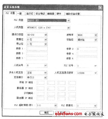
Figure 2 Parameter Setting Dialog
At this time, the operable address range of the touch screen is shown in Table 1.
Table 1 The range of operable addresses when the touch screen is set to MODBUS RTU touch
Ox1—Ox9999, 1 & TImes; 1-1x9999 are used for bit operation memory, 3xl—3x9999, 4xl—4x9999 are used for word operation memory. lxl-1x9999 is used as the input node (read-only) bit operation memory, as the bit status indicator on the touch screen. Oxl ~ oX9999 is readable and writable, and can be used as bit status indicator, button, trigger control and so on. 3xl-3x9999 as the input data storage, can be used as a numeric display element and multi-state indicator in the touch screen. 4xl-4x9999 can be read and written, and can be used as a numeric input element and multi-state setting element in the touch screen. The address is expressed in decimal numbers. OxO, lx0, 3xO, 4x0 cannot be used, otherwise errors will occur during compilation.
The register address corresponding to the touch screen can be freely defined and allocated in the single chip microcomputer.
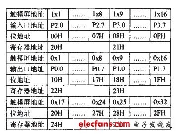
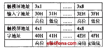
For example, assume that P2 and P3 are input ports, and P0 and P1 are output ports. In order to facilitate the programming of the single-chip microcomputer, the pin states of the P2 and P3 ports can be mapped to 20H and 21H, corresponding to the touch screen lxl-1x16. Save the data of P0 and P1 output ports to the registers 22H and 23H, corresponding to the touch screen 0xl to 0x16. 24H-28H as the bit operation storage area, corresponding to the touch screen 0x16-1x56. Set 30H-3F: H to 8 data display registers, corresponding to the touch screen 3xl-3x8. Set 40H-4FH into 8 data setting registers, corresponding to the touch screen 4x1-4x8. In this way, a correspondence table between the communication address of the touch screen and the single chip can be listed, and the bit address is shown in Table 2. The word address is shown in Table 3.
Table 2 Correspondence table between touch screen and MCU communication bit address

Table 3 Correspondence table between touch screen and single chip communication word address
3 Touch screen configuration software editing
Open the touch-screen configuration software, open the touch-screen configuration software, first set the [system parameters] in the above-mentioned methods, first set [system parameters], set the system parameters, move the cursor to [window / component selection list box], right-click, right-click, right-click, right-click, right-click, a new window, fill out the dialog box, fill in the dialog box according to the requirements, fill in the dialog box according to the requirements, fill in the dialog box, according to the requirements. Press the OK key, and an editing window appears. The following takes an example of setting a bit status display element (indicator light) and a value display element (data display window) to illustrate the method of establishing mutual contact between the address edited by the touch screen and the address in the microcontroller. Now let's take the example of displaying the state of 20H (24H.0) of the single-chip microcomputer and displaying the values ​​of 40H and 41H. Click the component diagram in the component toolbox or drag a bit status indicator component from the menu [component] option. And pop-up bit state display component properties dialog box.
Select 0x in [Device Type] in the reading address bar, and write [Device Address] to 17, as shown in Table 2. 0x17 corresponds to 20H, and select the appropriate figure, label, size and position. Press the OK key. The dialog box disappears and a bit status display element L1 appears in the editing window. Once the correct communication relationship is established, the different display states of this bit status display element reflect the changes in the bit 20H status of the microcontroller.
Click the mouse on the component diagram in the component toolbox or drag a numeric display component from the menu [component] option. And pop-up value display component properties dialog box. As shown in Figure 3.
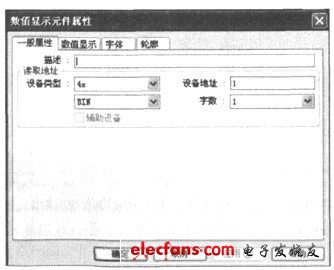
Figure 3 Numerical display element dialog box
Select [Class] in the reading address bar, and write [Device Address] to 1, as shown in Table 3. 3xl corresponds to 40H (high bit) and 41H (low bit), select the appropriate graphics, label, size and position. Press the OK key, the dialog box disappears.
A numerical display element appears in the editing window. Once the correct communication relationship is established, this numerical display element displays the values ​​of 40H (high) and 41H (low) in the single-chip microcomputer.
LED Street Light which semiconductor lighting, light emitting diode as light source, because it is a solid cold light source, green pollution-free, less consumption, high luminous efficiency, long service life etc, made of LED street light.
LED Street Light is applicable to road, highway, highways, urban streets, sidewalks and other road lighting and square, schools, industrial zone, parks and other outdoor lighting.
LED Street Light
LED Street Light,LED Solar Street Light,Adjustable LED Street Lighting,Solar Panel LED Street Light,Outdoor Light
Wenzhou Korlen Electric Appliances Co., Ltd. , https://www.korlenelectric.com