1 Definition of power factor
In order to characterize the utilization of AC power, the term power factor PF (PowerFactor) is introduced in electrotechnics and is defined as the ratio of useful power P to apparent power S, ie
PF = P/S (1)
With the improvement of the operational performance of the control technology of various industries, the electrical equipment in many occasions does not directly use the AC power provided by the universal AC network as a source of electrical energy, but transforms it by various forms to obtain Various forms of electrical energy required. Their amplitude, frequency, stability and variation are different depending on the electrical equipment, such as motor frequency converter, green lighting power supply, switching power supply, etc. After they are connected to the voltage network, there is also an AC power utilization rate. problem. The common feature of the above products is that AC/DC conversion is realized by bridge rectifier and large-capacity filter capacitor, and DC voltage is obtained by power frequency mains; although the AC input voltage basically has no waveform distortion, the input current is no longer Keep a sinusoidal waveform, but a pulse with a discontinuous peak. The bridge rectifier filter circuit shown in Figure 1. Only when the instantaneous value of the input AC power source Uac is higher than the voltage of the capacitor C, the rectifier diode is turned on, and the Udc remains substantially unchanged. The conduction angle of the visible diode is significantly less than 180°, and the input current waveform is seriously distorted.
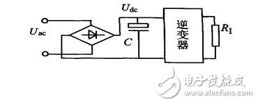
Figure 1 Bridge rectifier filter circuit
Let u(t) be the instantaneous power supply line voltage, i(t) is the instantaneous input current, T is the period of the input voltage, U and I are the effective values ​​of the input voltage and current, respectively.

1) For purely resistive and reactive loads in linear systems, the system input voltage and input current are in a standard sinusoidal waveform. There is a displacement angle 两者 between them. Let u(f)=Umsinωt i(t)=Imsin(ω +φ) Substituting equation (4) yields PF = cosφ.
2) If the input voltage of the system is a standard sine wave, only the fundamental component, that is, the rms voltage is the fundamental voltage, the input current is a non-sinusoidal signal, which contains the fundamental component and other higher harmonics. The effective value of the fundamental component of the current can be regarded as the orthogonal synthesis of the active component and the reactive component of the fundamental component φ1 is the phase angle between the input voltage and the fundamental of the input current. Therefore, P = UI1cosφ1, substituted into equation (4)
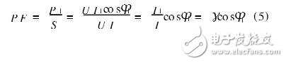
Let γ = I1/I be called the harmonic factor and cosφ1 the phase factor, so that the power factor is equal to the product of the harmonic factor and the phase factor. Let the instantaneous current i(t) be expanded by Fourier series as follows:
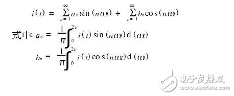
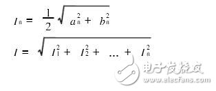
Where n is the harmonic order, for the nth current harmonic, the effective value In of the current and the effective value I of the input current are respectively
Defining total harmonic distortion
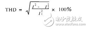
The formula (5) becomes
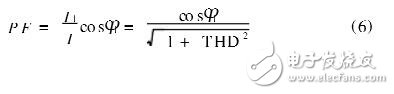
It can be seen that the line power factor is related to the waveform distortion of the input current, and is also related to the cosine of the phase between the fundamental voltage and current. If there is harmonic, the reactive power will be generated and the power factor will be reduced.
3) When the input voltage and current are not sinusoidal, equation (6) is no longer applicable.
2 Determination of the power factor of fluorescent lamps
There are two methods for testing the power factor measurement of the fluorescent lamp circuit in the course of electrical engineering and circuit principle. First, the power factor meter is used. The second is to use the three-table method shown in Figure 2, that is, the power meter and the voltmeter. Ammeter. Some use electronic ballasts and inductive ballasts to start fluorescent experiments to make students understand the significance of improving the line power factor, but there are two main problems when doing comparative experiments:
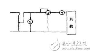
Figure 2 Three-table method to measure line power factor
(1) The instrument used is an ordinary electromagnetic or electric instrument;
(2) The test circuit used does not conform to the national standard as shown in Figure 3.
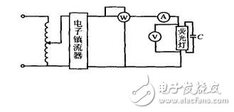
Figure 3 wrong test circuit
The normal power factor meter measures power and is only suitable for testing sine waves of 50Hz/60Hz. If the power factor of the power line, such as an electronic ballast, is severely distorted for measuring the input current waveform, as shown by equation (6), a very large measurement error must occur. When using the three-meter method, if the ordinary voltmeter, ammeter and power meter are used, the calculated line power factor has a large deviation from the actual one, and some results are close to 1, and even an error result greater than one may occur.
The author used different instruments to experiment with fluorescent lamps activated by different brands of 40W electronic ballasts and fluorescent lamps activated by magnetic ballasts. The measured data are as follows:
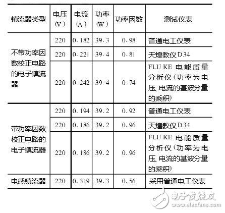
From the above experimental data, it can be seen that when the fluorescent lamp activated by the same electronic ballast is tested, the used instrument is different, and the obtained power factor is also different; for the electronic ballast without the power factor correction circuit, the ordinary electrician is used. Tested separately with FLUKE power quality analyzer, the latter is more accurate, the former has the largest error, and the main error comes from the measurement of the effective value of the current. The reason is that ordinary instruments measure non-sinusoidal signals containing a large number of harmonic components, and the measured results can only basically reflect the fundamental component, and there is a large error for higher harmonics. Secondly, it can be seen from the table that With the true RMS instrument, selecting an electronic ballast with a power factor correction circuit to start the fluorescent lamp for experiment can reduce the requirements on the instrument and reduce the experimental error.
To measure the power factor of the fluorescent lamp line, the correct method is to use the true RMS digitizer and use the correct wiring diagram (the national standard is GB/T15144). Because the inverter technology of electric energy is now widely used, the power factor correction circuit used in some products is not very effective, so that the power grid contains various harmonics; in addition, the operating frequency of the electronic ballast is several tens of kHz, so that after sampling The discrete signal is restored to the original signal without distortion. According to the sampling theorem, the sampling frequency is at least twice the frequency of the signal, and if the measurement error is limited to within a few thousandths, the above-mentioned digital instrument for measuring the power factor uses A. The /D converter should be at least 12 bits and the slew rate should be μs.
3 Conclusion
Power factor is an important concept. With the development of science and technology, its concept has a new connotation, and it also has certain requirements for measuring instruments. In the theoretical teaching, it should pay attention to its preconditions. The experimental equipment should use appropriate instruments and Ballast.
Multi-Functional Tower Socket,Black Vertical Tower Socket,2-Usb Vertical Tower Socket,4-Layers Vertical Tower Socket
Yuyao Huijun Electrical Appliance Co., Ltd. , https://www.yyhjdq.com