Phased array radars have developed rapidly in recent years, and phase shifters are an indispensable component in T/R. There is an electronically controlled phase shifter behind each radiating element to control the phase shift, so that the phase of the antenna aperture surface changes, and the beam is flexibly pointed. Here we mainly introduce the diode switch phase shifter
1, the difference between phase shifter and delay line
When I first touched the phase shifter, I subconsciously thought of using a short transmission line. In fact, the switching line phase shifter is a short transmission line, but the delay line is also a transmission line, the phase shifter and the delay line. What is the difference? My understanding is as follows:
Basic formula:  Phase shifter:
 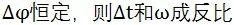 Delay line:
A transmission line is equally delayed for any frequency when there is no dispersion. Strictly speaking, the transmission line is a delay line. When the bandwidth is very narrow, the phase shifter can be implemented with a short delay line, which can achieve equal phase shift in a relatively narrow bandwidth, so the switch line phase shifter can only be used in narrowband situations.
In the case of a wide signal bandwidth, when the signal passes through the phase shifter, because of the different delays for each frequency, I personally understand that it is actually a dispersion effect, and I do not know whether it has an effect on the use of the system.
2, the implementation of the phase shifter
The phase shifter has several implementations as shown in Figure 1. It can be seen that both (a) and (d) allow the signal to produce a delay difference to achieve phase shifting. Figure (f) is the basic principle of a vector modulation phase shifter that uses orthogonal vector synthesis to produce phase shifting.
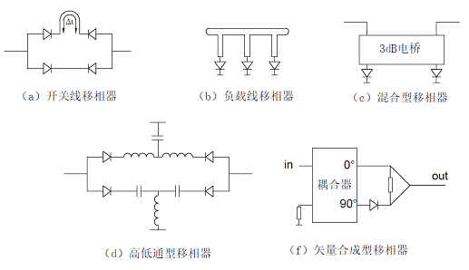
Figure 1 Phase shifter implementation
Personally think that hybrid, high-low-pass, vector synthesis is a structure that is more suitable for ultra-wideband applications. Share my understanding of each structure here.
a) Switch line phase shifter
The basic principle of the switching line phase shifter is to let the signal pass through two different lengths of transmission lines, resulting in phase shifting. Due to the constant, a larger phase shift (for example, 22.5°) can only be in a narrow bandwidth at high frequencies. The phase of the phase shift is constant. For ultra-wideband, such as 6~18G, this scheme is not ideal for small phase shift or large phase shift.
Fig. 2 Comparison of common phase shift performance of switch line phase shifters
b) Load line phase shifter
The circuit principle of the two states of the load line phase shifter to produce phase shift is shown in Figure 3. The result of generating a 45° phase shift is shown in Figure 4. It can be seen that the load line type can perform better in medium bandwidth and medium phase shift. However, in the case of ultra-wideband, the load line phase shifter is not very competent. Because of its own experience in filters and branch line bridges, the limitations of load line phase shifters in ultra-wideband applications are explained here by filters and branch line bridge theory.
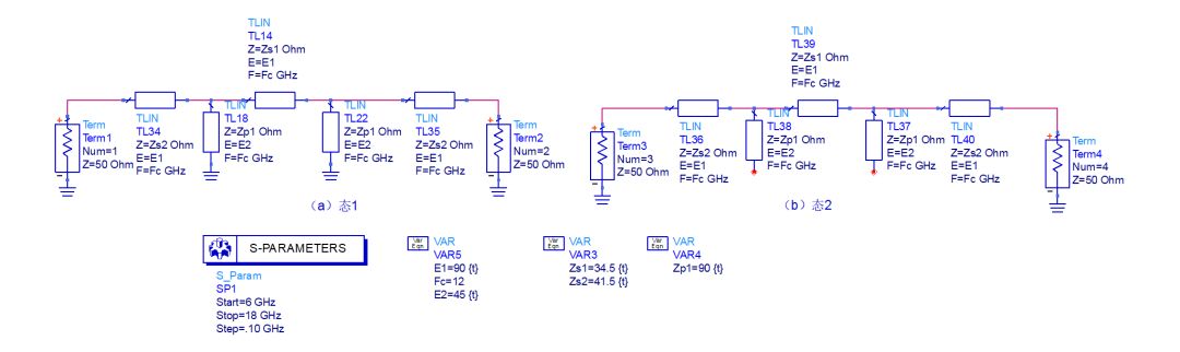
Figure 3 Two states of the load line phase shifter (switch on and off two states)

Figure 4 Results of the load line phase shifter at 45°
Filter Perspectives Explain the Limitations of Load Line Phase Shifters in Ultra-Wideband Applications
Careful observation of the structure of Figure 3 (a), it can be known that this is a typical planar high-pass structure, (detailed theoretical reference Microstrip Filters for RF / Microwave Applications Chapter 6), when the parallel wiring impedance is higher (line width When narrow, the lower the cutoff frequency of Qualcomm, the higher the cutoff frequency of Qualcomm when the parallel line impedance is lower (the wider the line width), the high-pass response of Figure 3(a) can be seen from the transmission response of Figure 4. .
Careful observation of the structure of Figure 3 (b), it can be known that this is a typical planar low-pass structure (detailed theoretical reference Microstrip Filters for RF / Microwave Applications Chapter 5), when the parallel connection impedance is higher (line width The narrower the lower pass, the lower the cutoff frequency of the low pass, and the lower the cutoff frequency of the low pass (the wider the line width), the lower the cutoff frequency of the low pass. See Figure 3(b) from the transmission response of Figure 4. Low pass response.
It can be seen from the analysis of the high-low-pass characteristics of the two states in Fig. 3 that the higher the line impedance (the narrower the line width), the wider the bandwidth of the phase shifter, and the lower the line impedance (the wider the line width), the narrower the bandwidth. . Extremely high parallel impedance lines are required for ultra-wideband applications, which limits the ultra-wideband applications of load line phase shifters. At the same time, the load line can be regarded as a special implementation of the high-low-pass phase shifter. In the phase shifter in the form of a load line, the high-low-pass sharing the transmission line structure.
Interpretation of the limitations of branch line bridges on the limitations of load line phase shifters in ultra-wideband applications
In the previous microwave note "Implementation of Bezier Waveguide Directional Coupler", the principle of the branch line bridge is explained by the odd-mode view. The odd-mode circuit (Figure 3(a) equivalent) realizes the phase shift of θ, even mode. The circuit (Fig. 3(b) is equivalent) achieves a phase shift of -θ, and θ can represent the degree of coupling. Therefore, an ultra-wideband branch line bridge with a certain degree of coupling is an ideal wideband phase shifter from the symmetry plane, but anyone who knows about ultra-wideband branch line bridges knows that this bridge is difficult to use with microstrips. Line or planar circuits are implemented because of the process limitations of high impedance lines.
c) Hybrid phase shifter
Hybrid phase shifters typically use larger phase shifts, such as 90° and 180°. The topology of the hybrid phase shifter is shown in Figure 5.
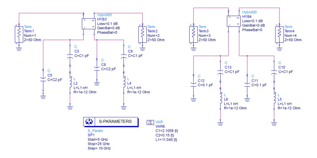
Figure 5 hybrid phase shifter topology
As shown, the phase shift bandwidth of this structure depends on the bandwidth of the phase shifting network at the two sub-power terminals. Large bandwidth and large phase shift can usually be achieved.
If the two sub-power terminals are directly short-circuited, the signal is input from the input terminal, and the output from the isolated terminal can produce a 90-degree phase shift, and a wide-band 90° phase shift can be realized by one switch.
d) high and low pass phase shifter
The high-low-pass phase shifter generates a different delay difference by switching the high- and low-pass signals, thereby realizing the phase shifting effect. By reasonably selecting the cut-off frequency and structure of the high-low-pass, the phase shift can be realized in a wide frequency band. For example, the high-low-pass structure of FIG. 5 can realize an 11° phase shift of 6~18G, and generally the shift phase of 5.6°, 11.2°, and 22.5° can be realized by a high-low-pass structure. When designing these numbers of phase shifters, it becomes how to design a switching high-low-pass filter.
A phase shifter actually implements a delay that varies linearly with frequency. The delay of the high-low-pass filter varies linearly over a period of time. Reasonable design and utilization of this trend is the key to designing a high-low-pass phase-shifting network.
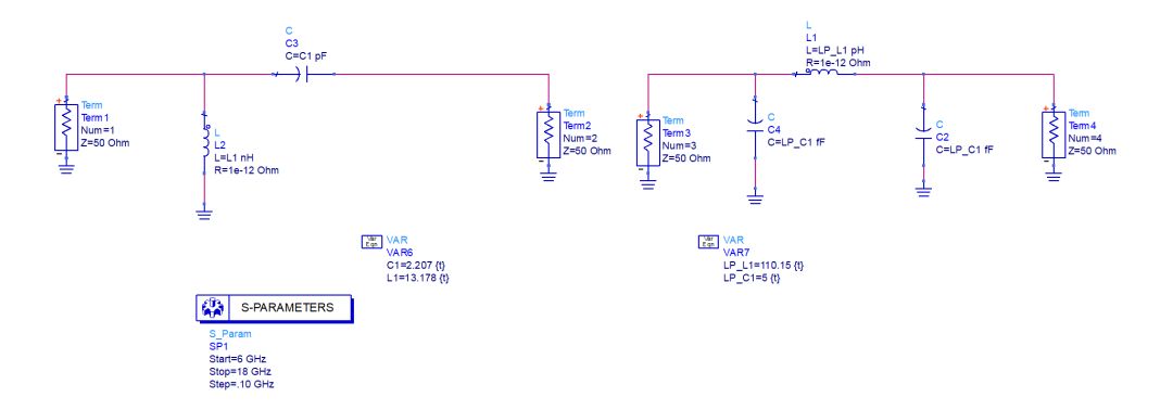
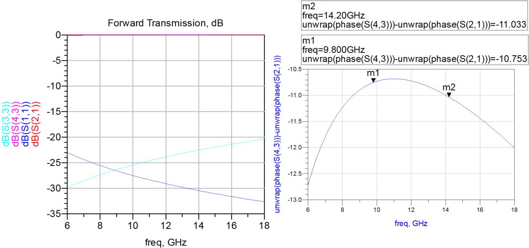
Figure 6 High-low-pass phase shifter for broadband performance
e) Vector composite phase shifter
The principle of the vector synthesis phase shifter is shown in Fig. 7. A two-way signal split by a 90° bridge with a specific coupling degree can be phase-shifted by the synthesizer, and the phase shift phase is the same as the voltage of two orthogonal signals. Related. This is also the working principle of the vector modulation phase shifter, which can achieve continuous phase shift in the wide range, such as phase shift accuracy of 1 °.
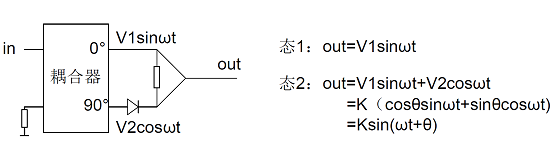
Figure 7 Principle of vector synthesis phase shifter
3. Summary
Since the phase shifter is limited to the theoretical level, it has only been used, but no practical design experience. According to the current understanding of the phase shift theory and its own experience in other broadband passive circuits, the possible topological structure of the UWB phase shifter is analyzed. The cognition is limited. It is expected that by communicating itself, it can also obtain a larger Upgrade.
We are dedicated charging solution Manufacturer since 2005.
Supply various Power Station including Portable Power Stations, Solar Power Generators, Smallest Generator etc.
Manufacturing high quality products for customers according to international standards, such as CE ROHS FCC REACH UL SGS BQB etc.
To constantly offer clients more innovative products and better services is our consistent pursuit.
portable power stations for camping, solar pow er stations, jackery portable power station
TOPNOTCH INTERNATIONAL GROUP LIMITED , https://www.micbluetooth.com