With the continuous advancement of urban smart grid construction, construction of improved automation of distribution network equipment, comprehensive improvement of grid management and control capabilities, and the construction of an intelligent RMU is extremely important.
The main function of the switch cabinet is to open and close, control and protect the power equipment during the power generation, transmission, distribution and power conversion of the power system.
The main components of the switch cabinet are circuit breakers, disconnectors, load switches, operating mechanisms, transformers, and various protection devices.
The manual operation of the switchgear requires the operator to operate on site, and the road will be delayed for a long time. If an intelligent remote control device is used, the work can be completed quickly.
The intelligent ring network cabinet is an integrated and integrated multi-function device, which is formed by combining once and twice.

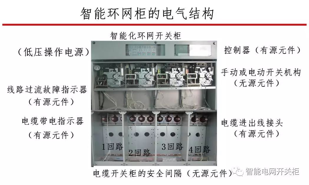
First, the division of electrical control cabinet components
Primary equipment refers to the high-voltage electrical equipment that is used directly in the production process of producing, transporting, and distributing electrical energy. It includes circuit breakers, disconnectors, automatic switches, contactors, knife switches, busbars, transmission lines, power cables, etc. The electrical equipment that is connected to each other by a primary device to form a switch of a power distribution device or perform a process of its closing and closing operations is called a primary device. Also known as a passive component.
Most of the load switch cabinets are manually operated. The primary equipment is divided into active components and passive components.
Secondary equipment refers to the low-voltage electrical equipment needed to monitor, control, regulate, and protect the work of the primary equipment and to provide operation and maintenance personnel with operating conditions or production command signals. Secondary equipment connected to each other constitutes an electrical equipment that monitors, controls, regulates, and protects primary equipment as a secondary equipment. Also known as active components.
Due to the different mounting positions of various electrical components, it is necessary to divide the components when forming a complete electrical control system.
1, equipment, a fusion design points:
(1) Combine similar functional components together;
(2) reduce the number of connections between components as much as possible, and place control devices with a close connection in the same component;
(3) Separate strong and weak electrical controllers to reduce interference;
(4) In order to achieve neat appearance, electrical appliances with similar dimensions and weight can be combined together;
(5) In order to facilitate the inspection and debugging of the electrical control system, it is necessary to combine the frequent adjustment, maintenance and wearing components.

2. In order to divide the components of the electrical control cabinet, it is necessary to solve the connection mode between the components, between the electrical boxes and between the electrical box and the controlled device:
The wiring between the various parts and components of the electrical control cabinet should generally follow the following principles:
(1) Switching electrical appliances, control board inlet and outlet lines generally use the terminal head or wiring nose connection, which according to the size of the current and the number of incoming and outgoing lines use different specifications of the terminal head or wiring nose;
(2) Electrical cabinets, control cabinets, cabinets (tables), and between them and the controlled equipment, connected by terminal blocks or industrial connectors;
(3) Various types of standard connectors should be used between weak control components and printed circuit board components;
(4) The connection between the components in the electrical cabinet, control cabinet and cabinet (table) can be directly connected by using the terminal of the component itself; the transitional connection line should be connected by terminal block transition, and the terminal should adopt the corresponding specification of the connection terminal. deal with.
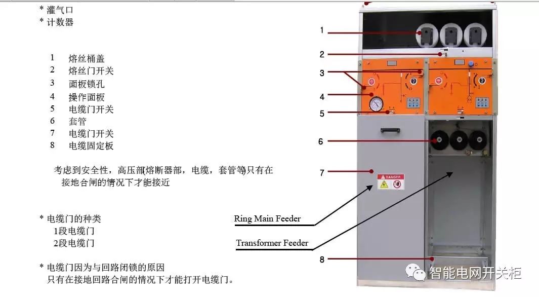
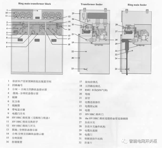
Second, manual switch cabinet structure
1, switch cabinet structure
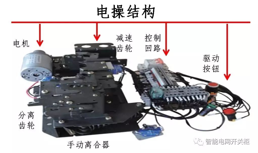
2. Switching and closing structure
3, a second fusion
The safety controller is an indispensable key equipment for distribution network automation, focusing on the local safety logic control implemented on the integrated switchgear. All signals required by the DTU are provided by the security controller.
When the DTU equipment is not installed, the electric operation of the RMU and remote signal and remote signal acquisition can be completed, and the electric operation of the switch cabinet can be completed independently. When the DTU equipment is installed later, there is no longer a need for a second power outage. It can be installed only when the controller is turned off.
Third, the key technology of intelligent ring network cabinet
With the gradual advancement and implementation of projects and projects such as the construction and renovation of distribution networks, a large number of manual switchgears need to be upgraded. In order to meet the technical requirements for the integration of secondary and secondary equipment after the transformation, a reasonable electrical control process design must be carried out. These designs include the structural design of the electrical control cabinet, the overall configuration diagram of the electrical control cabinet, the design of the overall wiring diagram, and the electrical assembly drawing and wiring diagram design for each part.
1, electrical switch controller structure design
2, the overall configuration of the electrical switchgear design
3, electric operation assembly and wiring diagram design
4, electrical control process design
4. Why can't the DTU terminal directly control the electric operation?
1. At present, the DTUs on the market are all direct-drive electro-mechanical actuators, and they are equipped with amplifier circuits and control loops.
2. When the DTU sends a command pulse for closing and closing, it is transmitted to the motor drive circuit of the electric operation. The motor is always in the electrified state and the operation power is turned on to complete a closed loop operation during the closing and closing operation. The disadvantage is that once the closing pulse is sent out, the DTU loses control and the electrical operation becomes an uncontrollable loop circuit.
3, install electric operation controller
The electrical control device (electro-operation controller) usually needs to make separate electrical control cabinets and boxes. Its design needs to consider the following aspects:
(1) Determine the overall size and structural type of the electrical box and cabinet according to the operational needs and the dimensions of the various electrical components in the control panel, box and cabinet. Under non-special circumstances, the overall dimensions of the electrical control cabinet should conform to the basic dimensions and series of the structure. ;
(2) According to the overall size and structure of the electric control cabinet, and the installation dimensions, design the mounting brackets inside the cabinet, and mark the mounting holes, mounting bolts and grounding bolt size, and indicate the configuration method. Cabinets, boxes of materials should generally use cabinets, boxes with special profiles;
(3) According to the requirements of on-site installation location, operation, and convenient maintenance, design the door opening method and type of electrical control cabinet;
(4) In order to facilitate the control of the ventilation and heat dissipation of the electrical appliances in the cabinet, ventilation holes or ventilation slots are designed in the appropriate parts of the cabinet. If necessary, forced ventilation devices and ventilation holes shall be designed in the upper part of the cabinet.
(5) In order to facilitate the transportation of electrical control cabinets, suitable lifting hooks should be designed or movable wheels should be designed at the bottom of the cabinet.
The installation of the electric operation controller is an intermediate device that plays the role of interface conversion of primary and secondary signals. The impulse remote command signal coming from the DTU terminal is converted into the driving current of the motor through power amplification of the controller. The electric operation driving circuit and the closing and grounding signal of all circuits on the switchgear cabinet are connected to the safety controller. Instead of the relay control circuit of each circuit above the switch cabinet, the integrated control of the RMU can be realized.
Primary and secondary equipment integration core key technology electrical operation safety controller
Without the installation of a DTU terminal, it is also possible to independently complete the safety control of the local electric opening and closing.
There is an automatic cabinet air pressure detection device on the controller. When the cabinet air pressure is found to be dangerous, the controller can automatically block all the motor drive circuits without the need of a DTU terminal to control the air pressure. At the same time, the controller logic cuts off. Current, prohibition of all switching operations.
Each circuit is provided with an automatic locking device. When a fault or dangerous message is found on the line, the locking button automatically jumps, locking the electric and remote operation of the circuit, and avoiding a wider range of faults caused by the closing and closing.

The terminal of each circuit is used for plugging and unplugging. If it is necessary to detect the opening and closing circuit on line, simply pull out the terminal and replace it with a simulator to conveniently perform the on-line switching test, which can not only complete the real-time test but also It will cause the effect of the switch action on the user.
The controller supports all types of DC24V operation mechanism downwards, supports different motor transmission methods (such as rocker transmission, gear transmission, chain transmission), and rotation direction (such as one-way positive rotation, one-way rotation of the motor, In both directions, the driving time is automatically set accurately. When there is no motor drive, the motor power circuit is not charged.
The controller upwardly supports various types of DTU terminals, and the full compatibility of the signals facilitates software debugging.
All signal terminals are plugged and unplugged to prevent various wiring errors. The safety controller functions as a connection device for interface conversion and information transmission and communication.
Fifth, electric operation steps
1 When operating the RMU through the controller in the field, first switch the 'Local/Remote' switch to the local position and the 'Latch/Unlock' switch to the unlocked position. Confirm the local indicator and unlock the indicator.
2 Closing and opening operations can be performed by pressing the 'Close/Open' button.
3 After closing or opening, the split/merge indicator will change. The split indicator display is consistent with the closing indicator on the manual operation panel.
4 After the operation is completed, switch the 'Local/Remote' switch and the 'Latch/Unlock' switch to the initial position before the operation.
5 The grounding switch cannot be operated electrically. When the grounding knife is closed, the controller split/closing button is automatically locked.
Sixth, the impact of manual operation on the controller
This controller implements the principle of manual operation priority. In any case, manual operation can be performed by using a spanner to open and close the cabinet and grounding switch. Insert the end of the manual operation handle with the keyway into the slot of the operation handle, which will not affect the controller. .
According to the direction indication, pushing the operating handle to the left (opening) or to the right (closing) will complete the operation to be performed. When the operating mechanism has the locking clutch, manual operation of the switch will not affect the electric mechanism.
After manually operating the switch structure, be sure to confirm the switch-off indicator on the operation panel.
Seven, electric operation precautions
Before operating, confirm the following:
Always check the pressure on the pressure gauge before closing, opening, or grounding. The pressure indicator on the gauge cannot be operated when it is in the red position. Must be in a green position to operate!
The main loop and the ground loop are interlocked. That is, the ground loop cannot be manually closed when the main circuit is closed, and the main loop cannot be driven when the ground loop is closed.
When operating the ground loop, check the voltage of the bushing end of the corresponding circuit. If a grounding operation is performed with a voltage at the bushing end, a 3-phase short-circuit fault will occur through the grounding bus.
After the operation is completed, the split/merge indicator on the safety operation controller will change. The display of the split indicator should be consistent with the closing indicator on the panel of the manual operation device. When the switch closes, the red closing indicator on the controller lights up. When the switch is opened, the green indicator on the controller lights up. This process is done automatically by the controller's sensor and no manual signal set is required.
The manual operation of the ground loop is the same as that of the main circuit. After the operation is completed, the ground indicator on the controller will change. If there is no grounding switch grounded, the controller grounding switch will not light up. After the grounding switch is closed, the grounding indicator on the controller will show yellow light. The ground indicator lamp must be displayed in the same way as the grounding state on the panel of the manual operation device. Otherwise, the operation process must be re-detected to find the cause of the error.
Mineral Insulated Cable,Copper Mineral Insulation Cable,Copper Core Copper Sheath Cable,Fire Resistant Cable
Baosheng Science&Technology Innovation Co.,Ltd , https://www.bscables.com