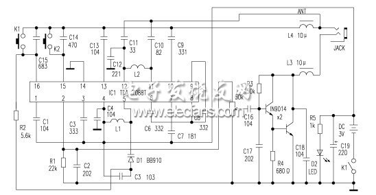
The pocket FM computer radio selected in this article uses the TDA7088T integrated block developed and produced by Philips. It uses a 16-pin dual-row flat package with an operating voltage of 3V. This circuit includes all functions of the FM radio receiving the frequency discrimination output audio signal from the antenna In addition, there is also a search tuning circuit, a signal detection circuit, a squelch circuit, and a frequency locked loop FLL circuit that compresses the intermediate frequency offset. The intermediate frequency of the TDA7088T circuit is designed to be 70kHz, and the intermediate circuit does not need an intermediate frequency transformer. The intermediate frequency is selected by the internal RC intermediate frequency filter. The machine uses an electric tuning button (RUN) like a digital tuning radio, and the other is a reset button (RESTE). After the circuit is powered on, press the search button, the circuit automatically searches for radio stations from the low frequency end to the high end. Once the radio signal is found, the tuning stops automatically. If you then press the search button, the circuit continues to search for radio stations on the high-frequency side. When tuned to the highest end of the FM reception frequency, just press the reset button, the local oscillator frequency returns to the lowest end, and search for tuning and start again. The following describes the production and debugging methods of the aircraft.
The machine uses a headphone cable as an antenna. The FM signal induced by the headphone cable enters the mixing circuit from the TDA7088T integrated block {11} pin, and generates a 70kHz intermediate frequency signal after mixing with the local oscillator. The radio signal is sent to the {11} and {12} pins of the integrated block. The inductor L2, capacitors C10, C11, and C12 form the input loop. The frequency of the circuit is determined by L1, C5, and the varactor diode D1. It can be seen from the figure that C1 is the noise suppression capacitor, C6 is the intermediate frequency feedback capacitor, C7 is the low-pass capacitor, pin {15} is the search tuning input, C14 is the filter capacitor, and pin {16} is the electrical tuning and AFC output. Solder the components to the circuit board according to the circuit diagram during assembly. Special attention should be paid here to the two air-core coils. The one with fewer turns is only the oscillating coil, which is installed between pins 4 and 5 of the integrated block. The other one with more turns is the input tuning loop coil, which is installed on {11} and Between the legs, because the IF frequency is chosen to be very low, the local oscillator signal can easily go from the antenna input to the circuit and cause interference, so the positions of the two coils should be placed perpendicular to each other. When soldering, pay attention to the pin arrangement direction of TDA7088T. Don't make mistakes. The soldering iron shell used for soldering should be grounded. Do not solder the components on the circuit board when the circuit board is energized. After the installation is complete, it is necessary to check carefully to avoid the phenomenon of wrong welding, virtual welding and short circuit, etc., and then carry out the next debugging work after confirming the correctness.
The mass production in general factories is to use the frequency sweeper to debug the radio. Amateurs do not have these instruments. They can be debugged with high-frequency signal generators or local FM radio stations. First connect a DC power supply to the {16} pin to increase the frequency coverage of the radio, and adjust the DC power supply to the voltage value of Vcc-0.1V (such as the power supply used by the radio Vcc = 3V then adjust to 3-0.1 = 2.9V), Adjust the inductance of the oscillating coil to adjust the inductance so that the radio receives a signal of 87-5MHz, and then adjust the DC power supply to the voltage value of Vcc-1.6V, as long as it can receive the signal of 108MHz. After the frequency coverage is adjusted, remove the DC power supply, that is, the assembly and debugging are completed. The receiving frequency of this machine is in the range of 88 ~ 108MHz (because the performance and pins of SC1088 integrated block and TDA7088T integrated block are the same, they can be directly substituted for each other). The circuit is shown in the figure above. Special specifications can adjust the receiving frequency of this machine to 76 ~ 106MHz, the size of this machine is only 78mm & TImes; 44mm & TImes; 14mm.
Product categories of LED Advertising Display includes MC Pro series Door Led Screen, MC Xs series Cross LED Display, MC Smart series Double sided Led Screen, MC Wall Wall Hanging Led Display,MC Air Showcase LED Display.
We are specialized manufacturer for small LED Advertising Display, mature supply chains are available to have competitive price. small LED Advertising Display is widely used in the door led screen industry, it gradually not only becomes the mainstream of the development now, but also city`s economic development coordinates.
We insist to offer novelty and unique appearance, adjustable size LED screen and will be indicate to supply customers a complete set of LED display solutions.
Display a Visual Future!!!
LED Advertising Display
LED Advertising Display,LED Display Screen,LED Advertising Screen,LED Display
Shenzhen Macion Optoelectronics Technology Co.,Ltd. , https://www.macion-led.com