0 Preface
In communication electronic circuits, it is necessary to amplify certain gains for small signals. The tiny signals in communication are all high-frequency signals , so the analysis of the circuit is based on the nonlinear characteristics of the period. There are many signal components with different frequency components in the output of the non-linear circuit, so it is necessary to use a resonant network with a frequency selection function to select the frequency. The performance of the resonant network frequency selection directly determines the performance of the resonant amplifier circuit. Using the observation of the time-domain waveform and the comparative analysis of the frequency spectrum of different frequencies in the frequency domain, the resonance amplifier circuit can be clearly analyzed.
1 Overview of resonance amplifier circuit
The LC parallel resonant circuit in the resonant circuit schematic diagram is replaced with a resistor Rc, which is a typical common emitter circuit. Its voltage amplification factor is Au = βRc / rbe (here is its absolute value, without considering the phase problem). Because Rc exhibits the same resistance (impedance) for all frequency components, this circuit has no frequency selection effect (that is, the amplification factor is the same in a wide frequency range). If Rc is replaced by an LC parallel resonant circuit, due to the frequency characteristics of the resonant impedance, a very high impedance is exhibited at the resonant frequency point and the very small frequency range around the left and right, so that the voltage amplification of the circuit is very high, and leaving the resonant point Other frequency ranges show extremely low impedance (ideally can be regarded as zero), so that the voltage amplification factor is close to zero, so this amplifier has a selective amplification characteristic for a certain frequency, called a resonant amplifier .

2 Time domain analysis of small-signal resonance amplifier circuit
In small-signal resonance amplification, there are unwanted signals in addition to the required signals in the input signal of the circuit, and their frequency spectra are often different, so the frequency selection method is used to select the required frequency components and suppress the unwanted frequency components. . In addition, the amplitude of the useful signal is often very small, and processing such a signal must have dual functions of frequency selection and amplification. The collector load of the transistor in the small-signal resonant amplifier circuit is an LC parallel resonant circuit, and its impedance changes with frequency. The impedance at the loop resonant frequency f0 is a pure resistance and is the largest, so the resonant amplifier is at the resonant frequency of the load loop With the largest gain of voltage amplification, the voltage gain will decrease rapidly when it is slightly away from the center frequency of this resonance. In the analysis, simulation software is used to test the input and output waveforms of the resonant amplifier circuit in the time domain. The analysis and test circuit is shown in Figure 2.
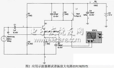
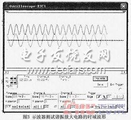
In the test circuit, the high-frequency small signal selects a 6MHz, 50mV sine wave signal, and the oscilloscope simultaneously tests the waveforms of the input and output signals. The input and output waveforms are shown in Figure 3.
The insert splitter is used for the user access point in the FTTX system, which mainly completes the optical fiber end of the residential area or building, and has the functions of optical fiber fixation, stripping, fusion, jumper and shunt, etc. After the splitter, it enters the end user in the form of household optical fiber.
There are currently 1 x N and 2 x N.1 x N and 2 x N evenly inputs the optical signal from a single or double inlet into multiple outlets, or work backward to integrate multiple optical signals into a single or double fiber.
PLC Insert Splitter,Insert Splitter,PLC Optical Splitter,PLC Fiber Splitter
Chengdu Xinruixin Optical Communication Technology Co.,Ltd , https://www.xrxoptic.com