At present, most home alarm systems on the market implement the alarm function through a telephone line. When the telephone line is maliciously cut, the system will lose the alarm function. In response to this problem, the mobile communication technology is introduced into the design of this system to avoid the occurrence of such problems. According to the cost performance and actual functional requirements, this system adopts single chip microcomputer and mobile communication technology to design the overall plan. The GSM / GPRS module is integrated with the single-chip computer, camera module and voice module to complete the communication between the single-chip computer and the GSM / GPRS module and the camera module, and a powerful home network anti-theft system is designed.

1 Overall system design
The mobile communication module in the system uses the PT39I module of Guangzhou Spectrum Technology Co., Ltd. The peripheral circuit is designed by itself, and connected with the mobile communication module through the RS232 serial port of the single chip microcomputer. According to the cost performance and the actual functional requirements of the system, the system uses the STC89C58 single-chip microcomputer as the controller, and communicates with the mobile communication module through the STC89C58 standard full-duplex serial port. First, the alarm signal collected by the sensor is sent to the single-chip microcomputer, and the single-chip microcomputer judges and sends the control command to the communication module. After receiving the command, the communication module calls the designed alarm short message and sends it to the user's mobile phone using the GSM network to realize the alarm function [1 ]. After receiving the alarm SMS, the user can reply the SMS to the alarm system, and the system will make a corresponding judgment based on the content of the SMS returned by the user, so as to issue a corresponding anti-theft instruction to the actuator of the control system. Use STC89C58 single-chip microcomputer as the control center, equipped with alarm collection module, mobile communication module, alarm module, actuator, camera, voice and other modules. The overall hardware block diagram of the system is shown in Figure 1.

2 System hardware components
2.1 PT39I module
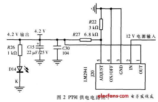
PT39I is a very typical wireless communication GSM module, which can quickly, safely and reliably realize the data function, voice function, short message service function and fax function in the system solution. The operating voltage is 3.4 V ~ 4.3 V, and the recommended voltage value in actual use is 3.8 V ~ 4.0 V. Working in three frequency bands of 900MHz, 1 800 MHz and 1 900 MHz, the power consumption of the frequency band is 2 W (900 MHz) And 1W (1 800 MHz and 1 900 MHz).
The constant voltage chip in Figure 2 is LM2941S. According to the electrical specifications of PT39I, the allowable voltage range is 3.4 V ~ 4.3 V. Therefore, you can directly connect the IO pin of the microcontroller to the 15th pin of the ZIF connector on the PT39I module to start The module needs to be loaded with a low-level signal of at least 100 ms. The start of the PT39I module is realized by the method of delay.
2.2 SCM selection
After comprehensive analysis at design time, a single-chip microcomputer with large memory is needed, so STC89C58 is selected, the memory is 1 KB RAM space, 32 KBROM space. During the design, 201 SMS data exchange spaces and 206 MMS data exchange spaces were divided. There are two reasons for using the crystal frequency of 22.118 4 MHz, one is to match the baud rate, and the other is to increase the data processing speed of the microcontroller.
2.3 SIM card circuit design
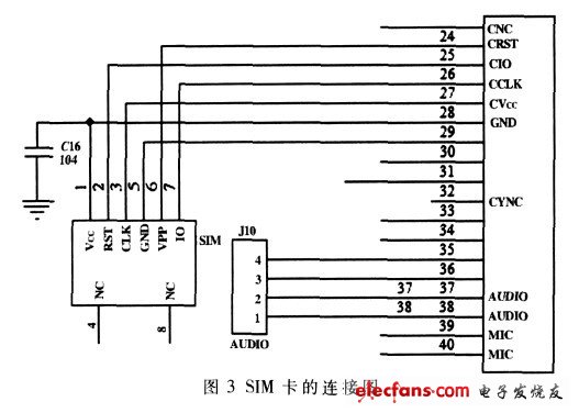
The SIM card is a chip with a microprocessor, which contains 5 modules, each module corresponds to a function: CPU, program memory ROM, working memory RAM, data memory EEPROM and serial communication unit, these 5 modules are integrated in In an integrated circuit. Therefore, when the SIM card is connected to the mobile phone, at least 5 connection lines are required: power (VCC), clock (CLK), data I / O port (Data), reset (RST), and ground (GND). As shown in Figure 3 Show.
Thermal printers are more smaller, lighter and consume less power, making them handheld Thermal Printer. Thermal printers are perfect mobile printer. Commercial applications of thermal printers include express, manufacturing, finance, ticketing, enforcement, warehouse, retail, parking and etc. Below is our advantages:
1. Mobile Bluetooth Printer, handy and stylish
2. USB/Bluetooth/RS232 various interface
3. Support label printing and receipt printing
4. Support Android/IOS/Win/Win CE/Symbian systems
5. High speed printing and high compatibility

Thermal Printer
Thermal Label Printer,Thermal Receipt Printer,Thermal Transfer Printer,Bluetooth Thermal Printer
Shenzhen Qunsuo Technology Co., Ltd , https://www.qsprinter.com