Hardware-in-the-loop real-time simulation platform of permanent magnet synchronous linear motor
Challenge: Using LabView 8.6.1 and two cRIO hardware and software platforms to quickly build a permanent magnet synchronous linear motor hardware-in-the-loop real-time simulation system.
Application Solution: Using NI LabView8.6.1, cRIO9074 and cRIO9004 software and hardware platforms, we successfully built a real-time hardware-in-the-loop simulation platform for permanent magnet synchronous linear motors. Among them, cRIO9074 and cRIO9004 are used for permanent magnet synchronous linear motor controller simulation and permanent magnet synchronous linear motor model simulation. Both use high-speed digital and analog data acquisition cards for data exchange, and their core algorithms are all completed in FPGA, with 50us High-level real-time characteristics.
Products: LabView8.6.1 / RT / FPGA; cRIO9074, cRIO9004, 9104; two 9401; 9215, 9264, 9205
Permanent magnet synchronous linear motors are currently widely concerned at home and abroad due to their excellent performances such as high speed, high precision and high rigidity. However, compared with traditional rotating electrical machines, linear motors are more difficult and dangerous to test. If improperly operated, it is extremely prone to flying, causing personal and property damage. Therefore, it is urgent to build a hardware-in-the-loop real-time simulation platform for permanent magnet synchronous linear motors. The rapid and successful construction of the simulation platform can verify the control algorithm of the linear motor in advance, thus facilitating the early detection of potential errors, saving debugging costs, shortening the debugging cycle and reducing the probability of accidents.
I. Introduction
The high-speed linear motion unit driven by the linear motor eliminates the intermediate transmission link from the servo motor to the worktable, and reduces the transmission chain of the motion unit to zero, which is called "zero transmission". The transmission mode can not only simplify the structure, but also improve the speed, acceleration, sensitivity, rigidity and accuracy of the linear motion unit. In the high-speed linear motion unit, it is a general trend to replace the traditional rotary motor with ball screw auxiliary drive by the linear motor directly. At present, the linear motor has been widely used in industrial, civil, military and other linear motion occasions. The well-known foreign machine tool companies, such as Siemems, Fanuc, etc. all use linear drive in their high-end CNC machine tools without exception, which greatly improves the accuracy and speed of the processed products. Permanent magnet synchronous linear motors have in fact become the future development direction of linear motors due to the advantages of no electric excitation, large thrust density and high efficiency.
Compared with traditional rotary motors, linear motors have an open magnetic circuit, and there is no mechanical transmission device buffer between the load and the linear motor. All disturbances are directly loaded to the motor end, plus the unique end effect of the linear motor. The control of linear motors brings great challenges. On the other hand, during commissioning and operation, there is a slight risk of the risk of speeding, which will cause personal and property losses. Therefore, this paper uses LabView8.6.1 and cRIO9074 and cRIO9004 software and hardware platforms to build a hardware-in-the-loop real-time simulation platform for permanent magnet synchronous linear motors. The platform uses vector control algorithm to achieve closed loop control of position loop, speed loop and current loop three loops or speed loop and current loop two loops. The platform can simulate a variety of motion conditions of permanent magnet synchronous linear motors and track speed and position reference signals quickly and error-free. The simulation results are similar to the Kollmorgen system, which verifies the correctness of the algorithm.
2. Mathematical model of permanent magnet synchronous linear motor
The dq axis equation of permanent magnet synchronous linear motor:

In equations (1) and (2), ud, uq, id, iq, Ld, and Lq represent the linear motor's straight, cross axis voltage, straight, cross axis current, and straight and cross axis inductance, R is the stator resistance, ![]() Is the permanent magnet flux linkage of the linear motor, V is the moving speed of the linear motor,
Is the permanent magnet flux linkage of the linear motor, V is the moving speed of the linear motor, ![]() Is the pitch and P is the number of pole pairs.
Is the pitch and P is the number of pole pairs.
The thrust equation of permanent magnet synchronous linear motor is:
In equation (4), Fd is the resistance of the linear motor (including the magnetic resistance and the resistance generated by the load), Bv is the viscous friction coefficient, and m is the mass of the linear motor (including the load). In equation (5), x is the displacement of the linear motor.
3. Vector control principle of permanent magnet synchronous linear motor
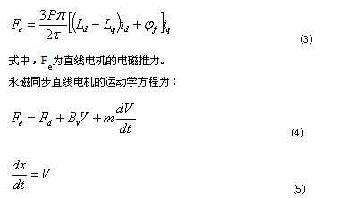
The vector control of the AC motor was proposed by German F. Blaschk and others in 1971. The basic idea is to simulate the torque control law of DC motor on AC motor. In the field-oriented coordinates, the current vector is decomposed into excitation current that generates magnetic flux and torque current that generates torque, so that the two current components are perpendicular and independent of each other, so they can be controlled separately. In the vector control system of permanent magnet synchronous motor, the position of the rotor pole is used to determine the trigger signal of the inverter to ensure that the inverter output frequency is always equal to the rotor angular frequency. Therefore, the vector control of the permanent magnet synchronous motor is operated automatically. Vector control. In vector control, the stator current control modes are various, and the current control mode and the rotor geometry affect the performance of the permanent magnet synchronous motor and the capacity of the converter. In this paper, the common straight-axis current id = 0 mode is used. The outstanding advantage of this control method is that there is no direct-axis armature reaction of the motor, which will not cause the demagnetization phenomenon of the permanent magnet, and the maximum thrust control per linear ampere of the linear motor can be achieved at the same time. By controlling the amplitude and phase of the stator current, you can obtain satisfactory thrust control characteristics. The block diagram of vector control proposed in this paper is shown in Figure 1.
4. Hardware-in-the-loop real-time simulation platform of permanent magnet synchronous linear motor
With the help of LabVIEW 8.6.1, cRIO9074, cRIO9004 and 9401, 9215, 9264, 9205 high-speed digital, analog acquisition card software and hardware platforms of NaTIonal Instruments, a permanent magnetic synchronous linear motor hardware-in-the-loop Real-time simulation platform. The platform uses vector control algorithm to achieve closed loop control of position loop, speed loop and current loop three loops or speed loop and current loop two loops according to needs. The maximum sampling frequency of current reaches 20kS / s (period 50us), which is higher than Kol Morgan The linear motor driver current sampling rate is 16kS / s (period 62.5us). The position and speed output of the system can track the given position and speed signals quickly and error-free. The accuracy reaches several micrometers. The controller parameters and linear motor load can be adjusted online. The simulation results are similar to the actual Kollmorgen system. The main functional modules of the platform are: parameter setting module, linear motor model simulation module, linear motor controller simulation module, graphic display module and data recording and analysis module. The schematic diagram of the platform is shown in Figure 2:

Parameter setting module: It is used to set linear motor parameters, load factor, viscosity friction coefficient, DC bus voltage, sampling frequency, initial controller parameters, triangle carrier frequency and amplitude, dead time in PWM module, etc. Among them, linear motor parameters, load factor, viscosity friction coefficient, DC bus voltage are used in the linear motor model simulation module (sampling frequency 100kS / s); initial controller parameters, triangular carrier frequency and amplitude, dead time in the PWM module Used for linear motor controller simulation module (sampling frequency 20kS / s). This part of the subroutine was successfully developed in the RT controllers of cRIO9074 and cRIO9004.
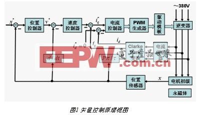
Linear motor model simulation module: the linear motor mathematical model and motion equation are used to simulate the actual linear motor operating state, and the obtained linear motor operation data is sent to the linear motor controller simulation module. According to the linear motor parameters obtained by the parameter setting module, the normalization processing is performed to obtain the normalized parameters of the linear motor. Collect 6-way PWM signals (using high-speed digital acquisition card 9401) sent by the linear motor controller simulation module, combined with the DC bus voltage and the current linear motor phase current positive and negative direction signals, calculate the linear motor three-phase phase voltage, proceed Clarke-Park transformation to get the dq axis voltage. Then according to the normalized linear motor dq axis equation, the next linear motor dq axis current, three-phase phase current, and electromagnetic thrust are calculated. Calculate the acceleration, speed, displacement, electrical angle and other signals of the linear motor according to the linear motor motion equation. Through the high-speed analog output card 9264, the five signals of the two phase currents, speeds, displacements, and electrical angles calculated above are sent to the straight line Motor controller simulation module. This part of the subroutine was successfully developed in the FPGA of cRIO9004 (interpolation 9401 and 9264). The subroutine block diagram of this module is shown in Figure 3.
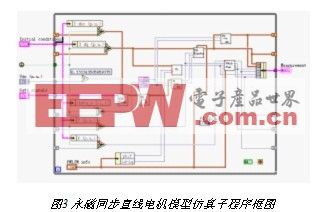
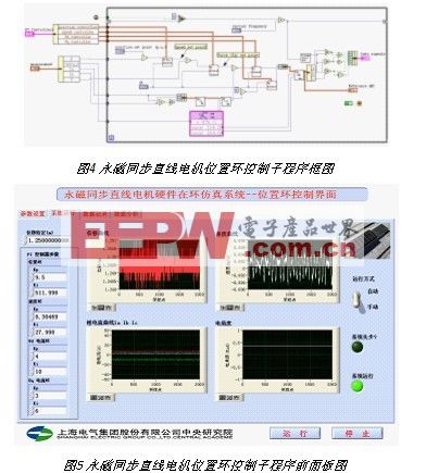
Linear motor controller simulation module: This module contains two subroutines of position loop, speed loop, current loop three loop and speed loop, current loop two loop closed loop control, to realize the closed loop control function of speed or position of the simulated linear motor. Take the position loop closed-loop control as an example to illustrate the main functions of this module. Using the 9215 and 9205 analog acquisition cards, the linear motor position, electrical angular velocity, two-phase linear motor phase current and speed signals from the linear motor model simulation module are collected. According to the position reference signal and the collected position feedback signal, the deviation value is obtained and sent to the position loop PI regulator, and its output is used as the speed reference signal. By analogy, the given voltage signals of d and q axes are obtained through the speed loop PI regulator and the current loop PI regulator (including d and q axes), and the three-phase phase voltage modulation signal is obtained through Clarke-Park inverse transformation. These signals are compared with the triangular carrier signal to obtain 6-way PWM signals including positive and negative (the algorithm considers the dead zone effect to prevent the short circuit of the upper and lower arms of the inverter), which is output to the linear motor model simulation through the 9401 high-speed data acquisition card Module, so far the entire linear motor position closed-loop control can be achieved. This part of the subroutine was successfully developed in the FPGA of cRIO9074 (interpolation 9401, 9205 and 9215). The block diagram and front panel diagram of the position loop subroutine are shown in Figures 4 and 5, respectively.
Graphic display module: real-time dynamic display of linear motor displacement, speed, three-phase phase current, position angle, PWM waveform curve. Real-time data exchange between the FPGA and the RT controller of the linear motor model simulation module and the linear motor controller simulation module through FIFO. This part of the subroutine was successfully developed in the RT controllers of cRIO9074 and cRIO9004.
Data recording and analysis module: access to linear motor displacement, speed, three-phase phase current, position angle, PWM waveform and other data, analyze linear motor current, voltage harmonic distribution, etc., to provide data for further optimization algorithm. This part of the subroutine is also successfully developed in the RT controllers of cRIO9074 and cRIO9004.
Three, simulation examples
3.1 Platform software and hardware components
The hardware and software of the permanent magnet synchronous linear motor hardware-in-the-loop real-time simulation platform are as follows:
Software platform: LabVIEW8.6.1 / RT / FPGA
Hardware platform:
l cRIO9074, 9401, 9205 and 9215 constitute the controller emulation hardware platform;
l cRIO9004, 9104, 9401 and 9264 make up the emulator simulation hardware platform
l One PC computer;
l Indoor network.
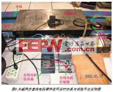
Figure 6 shows the physical diagram of the hardware-in-the-loop real-time simulation and test platform of the permanent magnet synchronous linear motor.
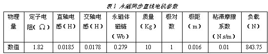
3.2 Parameters of permanent magnet synchronous linear motor
See Table 1 for permanent magnet synchronous linear motor parameters.
3.3 Simulation analysis
Figure 7 shows two different speed loop operation modes, automatic mode and manual mode, the former speed is given in ![]() 0.25m / s cycle jump, the latter keeps the speed given value 0.25m / s unchanged. From Figure 7, it is not difficult to find that by adjusting the speed loop and current loop controller parameters as a set of suitable parameters, as shown in Table 2, the simulated linear motor running speed can quickly track the speed given in about 10ms, and the steady state Error in
0.25m / s cycle jump, the latter keeps the speed given value 0.25m / s unchanged. From Figure 7, it is not difficult to find that by adjusting the speed loop and current loop controller parameters as a set of suitable parameters, as shown in Table 2, the simulated linear motor running speed can quickly track the speed given in about 10ms, and the steady state Error in ![]() Within 2um / s.
Within 2um / s.

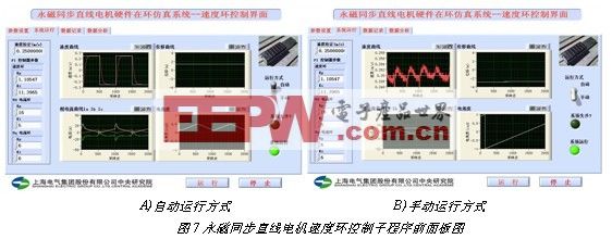
Figure 8 shows the PWM waveform in the linear motor simulator. It can be clearly seen in the figure that there is a dead time delay between the upper and lower edges of the three pairs of positive and negative PWM waveforms, which can avoid the IGBTs in the upper and lower arms of the inverter turning on at the same time, resulting in positive and negative output power of the inverter Risk of short circuit.
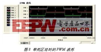
Figure 9 shows the simulation results of the position loop when the position setting values ​​are 0.25, 1.25 and 3.25m. The lower speed curve in the figure corresponds to the upper position setting curve. The parameters of the position loop, speed loop and current loop controller are as follows As shown in Table 3, see Figure 5 for the position loop interface.
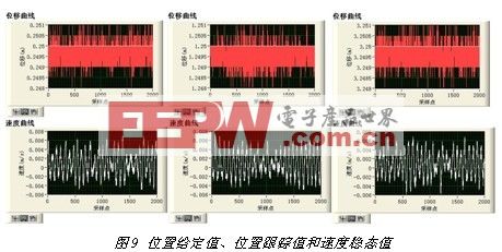
It can be drawn from Fig. 9 that for a given position value in the larger range of 0.25 ~ 3.25m, the position tracking error of the system is maintained between -1.5 ~ 1um, and the steady state value of speed is in the range of -0.005 ~ 0.007um / s Within the fluctuation, the system reaches a more ideal servo running state. The linear motor parameters in this paper are all taken from the actual linear motor parameters, and the operation results are consistent with the Kollmorgen system, thus verifying the correctness of the algorithm proposed in this paper.
4. Conclusion
Using NI's virtual instruments LabVIEW 8.6.1 / RT / FPGA, cRIO9074 and cRIO9004 / 9104 software and hardware platforms, a set of permanent magnet synchronous linear motor hardware-in-the-loop real-time simulation platform was built in a shorter time than other traditional The software development platform shortens the development time by at least one time. The successful development of the platform makes it possible to test the controller algorithm of the permanent magnet synchronous linear motor in advance under the condition of hardware in the loop. Therefore, in the actual driver development process, it will definitely save costs and shorten the development time, while reducing the probability of accidents.
Micro LED is a new kind of light source which has developed rapidly in recent years. LED light has been widely used for its advantages of small size, low power consumption, long service life, high brightness, low heat and environmental protection.
With the development of LED technology, more and more LED lights, and LED products LED copper wire in the lamp string not only applied to various festivals such as Christmas holiday decoration, and applied to a family to decorate and designs city-lighting project and all kinds of entertainment places.LED twinkle light has incomparable advantages with the traditional incandescent lamp series: colour is gorgeous, can realize a variety of color changes, and effectively reduce the energy consumption, composed of 7 colour color LED twinkle light can not only play the role of lighting, its adornment effect is to let different programs and different occasions add to the festive atmosphere.The LED copper wire lamp is about 0.38-0.5mm without soldering point, and it has high softness, flexible bending, arbitrary shape and not easy to be broken down.
[1]LED copper wire lamps are mainly used in the use of value: low power consumption, high efficiency, long life cold light source, long time lighting, rich color.
[ 2] LED copper wire light product use performance: easy installation, low maintenance rate, non-friable, high brightness, flexible, high temperature resistance, water proofing property is good, green environmental protection, low temperature, energy saving, high safety, light weight, small volume.[3]LED copper wire light application range: all kinds of strange new utility can be DIY products, such as clothes, bags, shoes, gloves, jewelry (necklaces, lei), bicycles, motorcycles and all kinds of car shine.Product classification editor
Classification by wire material.
A. Copper wire lamp string.
B. String of silver wires.
C. flexible string
D. copper enameled wire (available in any color, black, white, blue, green, etc.)
Sort by drive.
A. The battery box class LED lamp is equipped with 10-100pcs lamp beads, and the optimal configuration is below 50 beads.
1. 2*AA battery box.
2. 3*AAA battery box.
3. Waterproof 3*AAA battery box.
4. 2*CR2032 battery box.
5. 3*AG13 battery box.
6. Time switch battery box.
7. Multi-functional battery box.
Drive the classification chart.
Drive classification scheme (8 sheets)
B. There is no limit on the configuration of power transformer LED lamps, and the input voltage and LED quantity have a certain relationship as follows:
3 V(10-50 lamps);
4.5V(50 ~ 70 lamps);
6 V(100 ~ 300 lights);
12 V(above 300 lights);
24V(above 1000 lamps);
36 V(above 2000 lamps);
C. Solar energy: use the solar power to charge, put the lamp string controller in the sunny place, and hit the switch to (ON 1) or (ON 2).
D.USB power source:
E. Remote power source: the color change, speed change and brightness change of LED copper wire lamp are realized through the remote control device.
Classification by lamp beads.
A. ordinary rice grains.
B. Shape: such as heart, star, diamond, snowflake, petal, star, Christmas tree, Santa Claus, Christmas boots, etc.
Classification by appearance.
A.lamp string.
B.PVC tube light.
C. watefall lights
D. Cluster Lights
E.Cascade Lights F.icicle&curtain lights G.Tangle Free Item H. Figure Lights I.3D Acrylic
Use method editing
1- battery pack: install the battery, press the pull switch to install the product to any place you can install.
2- power transformer: the installation is simple and easy to use, just plug in the plug or switch on the battery box switch to power the power.Put the lamp around the place you want and set the shape you want.The humanized design of the product lets you eliminate the trouble of installation and use.
Specification editor
Common length, lamp distance, number of lights.
1M 20 lights (spacing 5CM)
5M 50 lights (spacing 10CM)
10m-100 light (spacing 10CM)
Micro LED Copper Light,Silver Copper String Lights,Copper Wire String Lights,Micro String Light
Heshan Jianhao Lighting Industrial Co., Ltd. , https://www.sunclubtw.com