This paper designs and implements a wireless sensor network with CC2430 as the core. The sensor module includes a temperature and humidity sensor SHT11, an infrared sensor BS520, and an illuminance sensor PGM5506. The overall structure of the wireless sensor network system The wireless sensor network is a technology for monitoring and managing information such as temperature, humidity, light, and acceleration of the surrounding environment. The wireless sensor node has a built-in sensor, a sensor control circuit, a CPU, a wireless communication module, an antenna, a power supply device, etc., and the Ad-Hoc communication technology can transmit data to the aggregation node together with the surrounding sensor nodes. The wireless sensor network described in this paper consists of a sink node and multiple sensor nodes, which are uploaded to the remote host through the aggregation node. The overall structure of the system is shown in Figure 1.
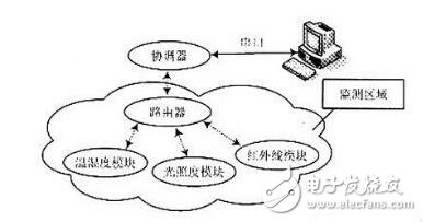
Figure 1 Overall composition of the system
Hardware circuit design
The CC2430 is a chip-on-chip system from Chipcon for embedded ZigBee applications. The CC2430 requires only a few external components to operate. It has a large number of necessary circuits integrated inside, so the signal transmission and reception functions are realized by using fewer peripheral circuits. Figure 2 shows the basic circuit design of the CC2430.

Figure 2 CC2480 basic circuit
In Figure 2, C1 and C2 are 22pF capacitors connected to a 32MHz crystal oscillator. This quartz crystal oscillator is used for normal operation. C3, C4 is a 15pF capacitor connected to a 32.768 kHz crystal oscillator circuit that operates during sleep to reduce power consumption. C5=O.1μF, used to remove some clutter interference and prevent the MCU from resetting incorrectly. C6 ~ C8 are 100 nF, 220nF, 220 nF, respectively, used as filtering to remove clutter interference and make the voltage more stable. C9=5.6 pF, the unbalanced transformer in the circuit is composed of capacitor C9 and inductors L1, L2, L3 and a PCB microwave transmission line. The whole structure satisfies the requirements of RF input/output matching resistor (50Ω). L1, L2 and L3 are respectively 8.2. nH, 22nH, 1.8nH.C10, C11, C12, C13, C14 are decoupling capacitors for power supply filtering to improve the stability of the chip operation. The bias resistors R1 and R2 are 43 kΩ and 56 kΩ, respectively. R1 is used to set the precision bias current for the 32 MHz crystal oscillator.
Due to the low power consumption of the CC2430 chip, two 2 800 mAh dry cells are used to power the node machine. The antenna uses an external antenna. CC2430 and temperature and humidity sensor SHTll, illuminance sensor PGM5506, infrared sensor BS520 connection schematic diagram shown in Figure 3, where P0.O, P0.1, P0.6, P1.2 and P1.3 are CC2430 I / O port .
SHTll uses two-wire serial line and processor for data communication, SCK data line is responsible for communication synchronization between processor and SHT11; DATA three-state gate is used for data reading. To avoid signal collisions, the microprocessor should drive DATA low. An external pull-up resistor is required to pull the signal high. Figure 3 shows pin P1.2 of CC2430 for SCK and P1.3 for DATA.
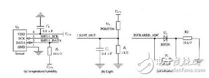
Figure 3 Schematic diagram of three sensor connections
The illuminance sensor PGM5506 is actually a photoresistor that changes the resistance value with the amount of light in the surrounding environment, so that the input 3 V voltage is affected by the photoresistor that varies with the amount of light, and thus the output voltage value changes. In LIGHTOUT which measures the output voltage value, the amount of light can be perceived based on the amount of voltage that changes. Figure 3 shows that pin P0.0 of CC2430 is connected to LIGHT OUT. Infrared sensor BS520. As the intensity of infrared light output A/D also changes, CC2430 processor can measure the infrared value according to the input current variation. Figure 3 shows the pin OP.1 of the CC2430 connected to the INFRARED ADC. Through the design of the wireless sensor network system and the understanding of the CC2430, the future application prospects of ZigBee technology are promising. In the next few years, it will be applied in many fields such as industrial control, automotive automation, building automation, and consumer electronics.
This battery is for replacing Lead-Acid Battery, it has the standard appearance and size as well as capacity, but longer cycle life and high energy and good charge and discharge performance.
Capacity:100AH/150AH/180AH/200AH/250AH.
Voltage:12.8V, cycle life is more than 2000 times, also can customize the capacity.
Lead-Acid Replacement Battery(LiFePo4)
Lead-Acid Battery,Lead-Acid Replacement Battery,Lifepo4 Lead Acid Replacement,Lead-Acid Replacement Battery(Lifepo4),12 Volt Battery Backup,Renewable Energy Bank
Shenzhen Enershare Technology Co.,Ltd , https://www.enersharepower.com