Based on the characteristics and application requirements of electric vehicles, the electromagnetic disturbance characteristics and propagation mechanism of the vehicle motor drive system are analyzed. The electromagnetic compatibility performance of the system is effectively improved by measures such as disturbance source suppression, system grounding, electromagnetic shielding and reasonable system layout. . The rectification scheme given in the paper has been applied to a pure electric vehicle, which meets the requirements of the national standard. The electromagnetic compatibility scheme given in the paper is effective.
The power electronic converters on electric vehicles far exceed the traditional cars in terms of quantity and power. The seriousness and complexity of electromagnetic compatibility problems are much higher than those of traditional cars. The motor drive system is one of the three key systems of electric vehicles and the most important power conversion device. Its electromagnetic compatibility performance (electromagneTIccompaTIbility, referred to as EMC) is not only related to its own work reliability, but also affects the safe operation of the whole vehicle. Ability and reliability of work. Judging from the existing inspection process of existing electric vehicle products, most of the models have been able to meet the relevant national standards after many rectifications. In view of the importance of electromagnetic compatibility, based on the general mechanism of electromagnetic disturbance coupling and propagation, this paper gives the electromagnetic compatibility analysis and solution of the motor drive system for electric vehicles, and gives the electromagnetic compatibility test results.
1 Electromagnetic disturbance analysis of motor drive system for vehiclesThe motor controller of the motor drive system of the vehicle is composed of a main circuit, a control circuit, a chassis, a radiator, and a cable. The main components of the main circuit are power modules, such as IPM or IGBT, which are the main sources of disturbance of the controller, and the parallel two wires form the inductance of the loop.
![]() (1)
(1)
Where: s is the spacing of parallel double lines; r is the radius of the wire.
At high frequency switching frequency (tens of kHz), high du/dt and di/dt are generated, which will generate high current spikes with the stray inductance of the DC bus; and the busbar of the motor controller for the vehicle The voltage is generally hundreds of volts, so the PWM wave is accompanied by a high voltage peak, which will inevitably lead to severe electromagnetic disturbance noise, which is caused by near-field and far-field coupling to form conduction and radiation disturbance. The PWM signal generated by the control circuit and the output high-frequency clock pulse also produce differential mode and common mode radiation, but the radiation level is low, and the electromagnetic disturbance generated is generally small. Poor shielding of the chassis can also cause electromagnetic interference caused by electromagnetic leakage. The heat sink generates electromagnetic oscillations. The heat sink usually has a complex geometry and has multi-band RF radiation characteristics, which is likely to act as a radiating antenna for the switching frequency harmonics. Unreasonable layout and non-shielding of cables can also cause large electromagnetic disturbances.
Another serious source of electromagnetic disturbance from the motor drive system comes from the motor. The motor is an inductive device that produces a strong pulse flow when the motor is operating and can travel through the power network to radiate into the surrounding space. The opening and closing of the motor and the change of load will cause the operating current to change and generate a pulse current. This disturbance appears as an irregular pulse flow with a spectrum of about 10 kHz and 1 GHz. Therefore, the motor drive system is the main source of electromagnetic disturbance for electric vehicles [2-3].
2 solutionsTheory and practice show that any electromagnetic disturbance must have three conditions: the source of the disturbance, the means of spreading the disturbance, and the sensitive equipment. The weakening or absence of any one condition will improve and solve the electromagnetic disturbance problem. Based on the above analysis, the electromagnetic compatibility design of the motor drive system developed this time adopted the following technical solutions.
2.1 Suppressing sources of disturbance(1) Designing the power busbar with low parasitic inductance: using the laminated busbar structure design technology [4], the positive and negative conductive copper plate and the intermediate insulator form a 3-layer structure, which can greatly reduce the parasitic inductance of the DC bus, thereby reducing the surge. Current and spike voltage. Figure 1 shows the design drawings for the busbar.

Figure 1 laminated busbar design
(2) For simplicity, a single-capacitor absorption loop is used to suppress high-frequency spike voltages and currents, and eventually consume or feed back into the power supply in the snubber circuit. The single capacitor absorption circuit is shown in Figure 2.

Figure 2 Single Capacitor Absorption Circuit
(3) Each IGBT gate drive is powered by an independent power supply, as shown in Figure 3, and uses a reverse bias voltage of -8V to avoid noise disturbance.
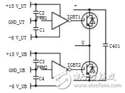
Figure 3 gate drive independent power supply
(4) Install EMI filter on the input side of the control power supply and power supply. As shown in Figure 4, it can reduce the electromagnetic emission intensity of the system and improve the anti-interference ability of the system. However, the impedance selection should be based on the operating frequency and impedance of the system. Features are matched.
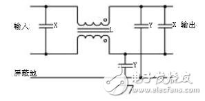
Figure 4 power EMI filter circuit diagram
(5) The drive motor is the strongest source of electromagnetic disturbance for the vehicle drive system. The motor casing forms a good seal to achieve the integrity of the shield, prevent electromagnetic leakage, and then shield the motor casing and the vehicle through multi-point grounding. Reliable grounding can effectively reduce the electromagnetic radiation level of the motor.
2.2 Elimination of propagation routes - grounding, decoupling, shielding design(1) According to the principle of ground separation. Separate the strong and weak ground wires, separate the digital circuit and the analog circuit ground, separate the lines safely, signal ground and noise, and finally converge to a common ground point; use photoelectric isolation to block the circulation and cut off the disturbance. The way; the outer casing and the radiator are reliably connected to the earth to prevent external magnetic field disturbance and electrostatic breakdown; flexible use of multi-point and single-point grounding.
(2) From the perspective of the system as a whole, it is one of the effective means to solve the system EMC by shielding the drive system to achieve good electromagnetic shielding effect. The key to electromagnetic shielding is to ensure the continuity of the shield. The chassis forms a continuously sealed conductor that reflects and absorbs the electromagnetic field coupled to the internal circuitry. Sealed by a soldering process at the permanent seam of the chassis; a solid conductive rubber strip is added to the non-permanent seam of the chassis as a conductive gasket to ensure the integrity of the shield. The shield continuity design of the power cable and signal cable through the chassis is also critical. The shield can be used with a shielded plug or socket or a power cable shield crimping device [5-6] at the termination. With the 360-term termination of the chassis and the use of a filter connector design, radiation coupling can be effectively suppressed. Figures 5 and 6 are schematic views of related measures.
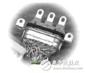
Figure 5 shielded power cable socket
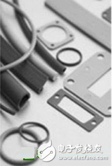
Figure 6 conductive gasket
2.3 Improve the immunity of the system(1) Reasonable overall layout. First, the strong and weak power are separated to avoid the influence of harassment between each other. Secondly, different power sources are used to supply the digital signal and the analog signal respectively to ensure that the signals of each other do not affect each other due to the power supply.
(2) Anti-interference design of the controller power supply. The control power supply uses isolated module power supplies, and different circuits are isolated and powered. Control power supply EMC design mainly has the following measures: First, the power input and output lines are twisted and combined to shorten the distance from the incoming end, and the common mode choke, sustain capacitor, decoupling capacitor and filter capacitor are added at the incoming end, as shown in Figure 4. Show. The second is to shorten the distance between the incoming end and the load, and increase the wire area to reduce the impact of the connection resistance on the load regulation.
(3) Anti-interference design of the control panel. The silt is electrically isolated; the component is derated; 盂 selects components with high integration; 榆 appropriately add filtering and decoupling circuits, such as a capacitor of 0.01 ray 0.1 滋F for each integrated circuit, and the capacitor The connection between the power supply terminal and the ground terminal of the chip is as short as possible; the data line, the address line, and the control line should be as short as possible to reduce the capacitance to the ground; the multi-layer partition design, the control circuit board adopts a multi-layer design, which can be effective To reduce the impedance of the power and ground lines and effectively reduce the loop area of ​​the circuit, this paper divides the control board into four areas, including the power supply area, the analog circuit partition, the digital circuit partition, and the isolated communication circuit partition.
3 Experimental resultsFigure 7 shows the block diagram of the system test configuration. The motor system adopts the speed control mode to simulate the actual running state of the vehicle. Among them, the motor is a permanent magnet synchronous motor with a peak power of 35 kW and a maximum speed of 6000 r/min.

Figure 7 system test block diagram
Figure 8 shows the results of the vertical polarization test of the radiation disturbance before and after the above-mentioned electromagnetic compatibility rectification scheme of the motor system, and the main frequency points are reduced by more than 50 dB. It can be seen from Fig. 8(a) that the over-standard of rectification without electromagnetic compatibility design is serious;
After rectification, the motor system passed the Class 3 requirements for radiated emissions of CISPR25:2008 components, as shown in Figure 8(b).

(a) before rectification
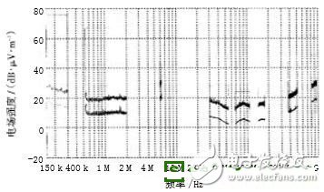
(b) after rectification
Figure 8 Radiation disturbance vertical polarization test results
4 ConclusionFor motor drive systems using power electronics, electromagnetic compatibility and interference suppression are undoubtedly critical. In view of the particularity of electric vehicles, this paper uses measures such as disturbance source suppression, system grounding, electromagnetic shielding, and reasonable layout of the system to effectively improve the electromagnetic compatibility of the motor drive system for vehicles. Through the application of a motor drive system for pure electric vehicles and the rectification and testing of various projects involved in the national standard, the correctness and effectiveness of the proposed scheme are proved.
China Fast Car Charger,Dc Fast Charging Stations manufacturers, welcome Electric Vehicle Charging Pile,Electric Charging Stations purchasers from worldwide to visit our site.
Fast Car Charger,Dc Fast Charging Stations,Electric Vehicle Charging Pile,Electric Charging Stations
Shenzhen Hongjiali New Energy Co., Ltd. , https://www.hjlcharger.com