OverviewThis application note describes how to use the DS31256's receive BERT function to perform Fractional-T1 (FT1) loop-up or loop-down detection (V.54) as described in the Fractional T1.403 Annex B spec. The operational algorithm and coding examples illustrate the easy adaptation of the DS31256 for end-user applications.
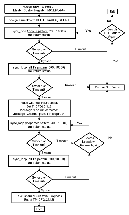
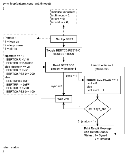
The DS31256 has only one BERT engine, but has 16 V.54 engines (one per port). Consequently, the software bandwidth must handle the multiplexing required if more than one port is tested. AlgorithmThe flowchart in Figures 1 and 2 below describes the loop -up and loop-down operation in detail. It is assumed that only port 0 is looking for the FT1 pattern. The basic algorithm sets the BERT to look for the loop-up pattern. After syncing up, the algorithm checks to ensure that the BERT is in sync for a programmable period (0.6 second in the code) and then looks for an all ones pattern. The same syncing and checking approach is then followed for the loop-down code, followed by the all ones pattern.
Although this example uses 0.6s as the period for ensuring that the BERT is in sync, this time period must be adjusted based on how fast the sync_loop function executes.

Figure 1. Flowchart of FT1 (loop-up and loop-down) detector operation.

Figure 2. Flow chart of FT1 (loop-up and loop-down) detector operation (continued). Definition of the Coding Example Function Calls Before looking at the code specifics, there are some assumptions that must be understood. The following functions are needed in the software. write_reg (addr, data) —writes the specified data value to the specified DS31256 register: addr = DS31256 register offset from the chip base address data = data to be written to register read_reg (addr) —reads the DS31256 register at the specified address and returns the value: addr = DS31256 register offset from the chip base address write_ind_reg (addr, data) —write the specified data to the specified DS31256 indirect select register, and then wait for that register's busy bit to clear before returning: addr = the indirect select register where data is to be written data = the data to be written to the specified indirect register read_ind_reg (addr, i) —read the DS31256 indirect register at the specified address and returns the value: addr = DS31256 register offset from the chip base address i = index The standard C print function, printf Coding Example of Functions Function to Test the FT1 void FT1Test () {int status = 0; FT1Setting (0, 0) ;-Configure the device for BERT status = sync_loop (1, 300, 5000);-FT1 loop-up test if (status == 1)-Return status is synced {status = sync_loop (3, 300, 5000) ;-FT1 all ones test if (status == 1) {loopbackSetup (1);-Place channelized in network loopback status = sync_loop (2, 300, 5000);-FT1 loop-down test if (status == 1) {status = sync_loop (3, 300, 5000);-FT1 all ones test if (status == 1) loopbackSetup (0);-Take out from channelized loopback else checkstatus (3);-Print out test status} else {checkstatus (2);-Print out test status}} else {checkstatus (3);-Print out test status}} else {checkstatus (1);-Print out test status}} 1. Function to Print Out the Test Status Message void checkstatus (int type) {switch (type) {case 1: printf ("Loopup pattern not found"); break; case 2: printf ("Loopdown pattern not found"); break; case 3: printf ("All 1's pattern not found"); break;}} 2. Function to Configure the FT1This examples assumes that Port 0 is used for FT1 detection
void FT1Setting (int dev, int port) {int mc = 0;-Variables to be used int ds0 = 0; int rcfg = 0; mc = read_reg (0x10);-Read Master Control (MC) 0x00 register mc = mc & 0xf07f;-Mask out the read-back value from MC write_reg (0x10, mc);-Assign the BERT to port 0 (MC.BPS4-0) write_reg (0x0304, 0x4000);-Configure port 0 in receive port for (ds0 = 0; ds0 <128; ds0 = ds0 + 1)-Configure register {--Assign timeslot R [0] CFG [ds0] .RBERT bit write_ind_reg (0x0300, 0x0100 + ds0);-Assign all 128 ds0's to RBERT} printf ("FT1 configuration completed.");} 3. Function to Perform the FT1 Test int sync_loop (int pattern, int sync_cnt, int timeout) {int timeCnt = 0;-Variables will be used int cnt = 0; int status = 0; int temp = 0; int sync = 0; int bertc0 = 0; int bertec0 = 0; BertSetup (pattern);-Set up the BERT bertc0 = read_reg (0x500);-Toggle RESYNC bertc0 = bertc0 | 0x0001;-Mask the read BERTC0 value write_reg (0x500, bertc0);-Write a 1 into BERTC0.RESYNC bertc0 = ber tc0 & 0xfffe;-Mask out read-back value write_reg (0x500, bertc0);-Write 0 into BERTC0.RESYNC bertc0 = read_reg (0x500);-Read BERTC0 bertec0 = read_reg (0x518);-Read BERTEC0 sync = ((bertec0 & 0x0001) == 0x0001); timeCnt = timeCnt + 1; while (cnt = timeout) {printf ("Time Out while searching for pattern."); return status = 0;}} delay (2000); timeCnt = timeCnt +1; bertec0 = read_reg (0x518);-Read value of BERTEC0 temp = ((bertec0 & 0x0010) == 0x0010);-Check BERTEC0.RLOS if (temp == 1) {sync = 0; cnt = 0;} else {cnt = cnt + 1;} if (cnt == sync_cnt) {printf ("Synced to pattern."); return status = 1;}} return 0;} 4. Set Up the Pattern in BERT Register void BertSetup (int pattern) {switch (pattern) {case 1: write_reg (0x500, 0x0 & 0x003c);-Disable BERTC0.RINV break;-Set 2E7-1 pattern case 2: write_reg (0x500, 0x0020 & 0x003c);-Enable BERTC0.RINV break;-Set 2E7-1 pattern default: write_reg (0x508, 0xffff);-Set BERT Repetitive Pattern Set write_reg (0x50C, 0xf fff);-in BERTBRP0-1 write_reg (0x500, 0x0010 & 0x003c);-Disable BERTC0.RINV break;-Set to repetitive pattern}} 5. Function to Set Up Loopback Mode This example assumes that Port 0 is placed in loopback. void loopbackSetup (int val) {int a = 0; int tmp = 0; tmp = val << 11; write_reg (0x0304, tmp);-Set port and channel 0 for (a = 0; a <128; a ++)-Set T [0] CFG [a] .CNLB to place channel in {-loopback write_ind_reg (0x0300, 0x0200 + a);} if (val == 1) {write_reg (0x0200, 0x0008);- Enable TP [0] CR.TFDA1 to allow data to printf ("Loopup detected");-be transmitted normally printf ("Channel placed in loopback");} else {write_reg (0x0200, 0x0000);-Disable TP [ 0] CR.TFDA1 bit printf ("Loopdown detected"); printf ("Channel taken out from loopback");}} ConclusionThis application note shows how to use the receive BERT function in the DS31256. The sample code and software algorithm illustrate how easy it is to perform FT1 loop-up or loop-down detection.
If you have further questions about our HDLC controller products, please contact the Telecommunication Applications support team by email at: var name = "telecom.support @"; var domain = "dalsemi.com"; document.write ("" + name + domain + ""); telecom. or call 972-371-6555.
Computer Mini Fan: This desk mini fan can be connected to a computer or a notebook to make your work or study more comfortable.
Strong wind and no noise: The computer Usb Fan uses a Hall DC motor to provide strong wind while quiet, energy-saving and stable operation and will not influence you or others.
The arm of the mini fan can be adjusted and the head can be rotated to about 105 degree.
With USB cable: USB port rechargeable, powered by lithium polymer battery, our mini usb computer fan comes with usb cable which can be charged with computer, power bank , mobile power and other devices.
With the gentle wind, just enjoy your happiness time. Different colors for choosing to make your life more colorful.
Mini Cpu Fan,Small Computer Fan,Small Pc Fan,Mini Pc Fan
SHENZHEN HONK ELECTRONIC CO., LTD , https://www.honktech.com