Keywords: ML4664, fiber optic transceiver, communication
1 Introduction With the continuous growth of the information user group and the increasing requirements of users for information service quality, optical fiber transmission stands out from various network transmission technologies, the construction of optical fiber networks is gradually expanding, and the application of optical fiber network products is also increasingly popular. Began to consider using "fiber-to-desktop" to replace copper cables in horizontal cabling systems. But consider a complete solution of fiber-to-desktop, not only fiber optic information outlet and fiber distribution box, but also expensive fiber optic network card and light outlet hub, which greatly increases the cost of the entire system. And a cost-effective way to achieve fiber-to-desktop is to use fiber optic transceivers (ie, photoelectric media converters). Optical fiber transceiver is a transparent transmission photoelectric medium conversion device, which can not only greatly simplify the upgrade of the local area network, but also protect the investment of the original copper cable LAN equipment, so it has become one of the urgently needed equipment in the current market.
2 System Structure The optical fiber transceiver system structure introduced in this paper is shown in Figure 1. It consists of photoelectric medium conversion chip ML4664, optical transceiver integrated module, electrical interface module, RJ45 and power supply. Among them, the photoelectric medium conversion chip ML4664 is the main chip of the optical fiber transceiver system, which completes the conversion of the 10Base-T twisted pair medium to the 10Base-FL fiber medium; the electrical interface module in addition to coupling the electrical signal sent by RJ45 to the ML4664 , Also includes a low-pass filter to complete the low-pass filter function; the optical transceiver module is an interface module with fiber optic media; because ML4664 requires digital power and analog power, so in the power section, we specifically divided the digital power and Two parts of analog power supply.

3 ML4664 function introduction ML4664 is a high-performance photoelectric medium conversion chip that Micro Linear company puts on the market. It can be used to realize the conversion of 10Base-T twisted-pair media to 10Base-FL fiber media. It is an ideal photoelectric medium conversion chip with 10Base-FL standard and adopts 5V power supply, and does not need external crystal or crystal oscillator. With the rapid development of optical communication, ML4664 will surely have wider application.
3.1 Main features The main features of ML4664 are:
· Support full duplex mode;
· Support 100Ω unshielded twisted pair and 150Ω shielded twisted pair;
The current output can be as high as 100mA, and has low RFI noise and very little jitter;
· With automatic polarity correction function;
· Input sensitivity up to 2mVP-P;
· With automatic connection detection function;
With a digital equalizer with high stability, it supports a dynamic input range of 55dB.
3. Introduction of 2 pin functions ML4664 is a 28-pin PLCC package, as shown in Figure 2.

(1) TPINPTPINN twisted pair data differential input terminal;
(2) TPOUTN TPOUTP twisted pair data differential output terminal;
(3) TPLED twisted pair data connection status indicator pin, when the connection is normal, the output is low level;
(4) POLDIS twisted pair data input status indication pin, through high and low level transitions, to indicate that there is data input;
(5) Output pin of OPOUT optical signal;
(6) Differential output terminal of OPINN OPINP optical signal;
(7) OPLED optical signal connection status indicator pin, when the connection is normal, the output is low level;
(8) LMON optical signal input status indicator pin, through high and low level transition, to indicate data input;
(9) AVCCVCC analog power supply and digital power supply;
(10) AGND GND analog ground and digital ground;
(11) RRSET is pulled up to the power supply through a 61.9K resistor as the external bias of the chip;
(12) RTSETOP sets the size of the output current, generally a 115Ω resistor can be used to pull it to the power supply;
(13) RTSETTP twisted pair impedance matching setting terminal, if you use 100Ω unshielded twisted pair, you can connect a 220Ω resistor between this pin and the power supply; if you use 150Ω shielded twisted pair, then connect 300Ω The resistance;
(14) TxCAP0 TxCAP1 sets the pulse width before equalization, and can be connected to a 680pF capacitor.
3.3 Working principle The internal circuit of the ML4664 chip is mainly composed of two parts: OP transmission and reception part; TP transmission and reception part.
OP's transmission and reception circuit mainly completes two functions: detect whether there is data input from TP and send the data into the optical transceiver integrated module. OP's transmission and reception circuit has a strong optical fiber signal detection capability, it can identify 2mVP-P, and the dynamic range of 55dB optical signal. OP's transmission and reception circuit drives the optical transceiver integrated module in the form of current. Before the data is sent to the optical transceiver integrated module, the excess noise must be filtered through the noise suppression circuit. The external resistance of the configuration pin RTSETOP can change the size of the output drive current IOUT. The corresponding formula is as follows:
![]()
Before the data is sent to the twisted-pair media, the noise must also be filtered out by the squelch circuit. The output of the TP signal must first pass a 2: 1 transformer, after low-pass filtering, and finally connected to the twisted pair through RJ45. The output form of the TP signal is voltage mode, and the output voltage is determined by the current value flowing into the TPOUTP and TPOUTN pins and the impedance of the output medium. ML4664 / ML4669 supports 100Ω unshielded twisted pair and 150Ω shielded twisted pair. The following formula determines the impedance of the twisted pair:

Where RL is the impedance value of the twisted pair. The TP transmission and reception part also integrates a pre-equalization circuit to compensate for the distortion of the signal amplitude and phase after transmission through the twisted pair. The attenuation of the 10MHz signal of the twisted pair is greater than that of the 5MHz signal. The front equalization circuit can make the amplitude of the 10MHz and 5MHz signals from the far end basically the same. When the TP transmission and reception circuit detects that there is no signal input on the pins OPINP and OPINN, the TP transmission circuit will enter the 'idle' state. At this time, an output voltage of only 450mV will be generated. This output voltage will continue to jump once after 250ns And back to 450mV.
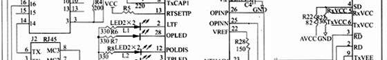
4 System Design of Optical Fiber Transceiver In the 10M optical fiber transceiver system we developed, ML4664 chip is used as the main chip for photoelectric medium conversion, and the electrical interface module uses chip SF1301.
Among them, SF1301 is responsible for coupling the electrical signal to ML4664 and performing low-pass filtering. RTXM15-14 is an integrated optical transceiver module, which converts the current signal output from ML4664 into an optical signal. The working process of the whole circuit is roughly as follows: The optical signal is sent to RTXM15-14 through the light, and the optical signal is converted into a differential current signal by RTXM15-14. The current signal is AC coupled and sent to ML4664. After a series of processing in ML4664 Then, low-pass filtering is performed by SF1301, and finally RJ45 is connected to complete the conversion process from optical signal to electrical signal.
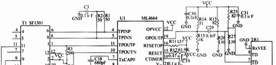
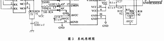
The differential signal transmission between RTXM15-14 and the main chip ML4664 adopts AC coupling, that is, connected through capacitors C27 and C28, so that the DC levels on both sides can be isolated, so that the RTXM15-14 and the main chip ML4664 can use different DC level deviations Reset scheme. It should be noted that at the output end of the ML4664 optical signal, there is only one pin OPOUTP, and the output pin of the optical transceiver integrated module requires a pair of differential signals TD and / TD, at this time the optical transceiver integrated module TD The pin is connected to a fixed DC level, and the other / TD pin is connected to the OPOUTP pin of ML4664 through capacitive coupling.
4.1 Initialization configuration The main chip ML4664 of this system is highly integrated, so the configuration of its peripheral pins is more troublesome. After many improvement experiments, we have found a series of better initialization configuration solutions. As follows: RTSETTP pin is externally connected with a resistance of 220Ω, so that the optical fiber transceiver supports 100Ω impedance of unshielded twisted pair; an external resistance of 61.9kΩ is connected to the RRSET pin to meet the needs of the internal bias of the chip; Indirectly, a 115Ω resistor makes the current output from the chip to the optical transceiver module about 52mA; the capacitance between TxCAP0 and TxCAP1 is mainly the pulse width before setting, and the size is preferably 680pF; the external capacitor of the CTIMER pin is set To detect the interval time value of the link status, a capacitor with a size of 0.047 μF can be used.
4.2 Power supply scheme and PCB wiring scheme The photoelectric medium conversion chip ML4664 requires the separation of the analog power supply and the digital power supply, the analog ground and the digital ground, and the power supply of the receiving part and the power supply of the transmitting part of the integrated optical transceiver module. Our processing scheme is as follows: The 5V power supply first passes the two 10μH inductors (L1, L2) to obtain the digital power supply VCC and the digital ground GND, and then passes the 1.2μH two inductors (L6, L7) to separate the analog power supply AVCC And analog ground AGND; the digital power supply VCC obtains the transmission power TxVCC of the optical transceiver module through the inductor L4, and the analog power supply AVCC obtains the reception power RxVCC of the optical transceiver module through the inductor L3.
In order to reduce electromagnetic interference, some special treatments were also carried out during the wiring of the PCB board. We use a four-layer board wiring scheme. In addition to the signal lines, the top and bottom layers must be grounded. The middle two layers are the power layer and the ground layer. The connection between the optical transceiver module and SF1301 to ML4664 are differential mode signal pairs. These differential mode signal pairs should be as close and parallel as possible to each other, and away from other signal lines. Moreover, the trace length of the differential mode signal line should be Keep it as short as possible to reduce its self-inductance. In addition, the reception signal line and the transmission signal line should be separated in two layers. If the reception signal line goes on the top layer, the transmission signal line needs to go on the bottom layer.
4.3 Selection of integrated optical transceiver module Fiber modes are divided into single-mode and multi-mode. According to the mode of the connected optical fiber, the integrated optical transceiver module can be divided into single-mode integrated optical transceiver module and multi-mode optical. Transceiver integrated module. Single-mode fiber has a low attenuation rate, long transmission distance, and large capacity, but it is expensive and often used in long-distance telecommunications; while the performance-price ratio of multi-mode fiber in short-distance transmission is better than that of single-mode fiber, so it is mostly used for shorter transmission distance. 'S network. The single-mode optical transceiver module uses a laser as the light source, and the multi-mode module uses light-emitting diodes. In addition, the integrated optical transceiver module has a long wavelength and a short wavelength; the interface types are ST, FC / PC, D4, SC, etc. Which type of integrated optical transceiver module to choose depends on the specific application environment. The optical fiber transceiver we designed has fully considered the compatibility issue. The optical transceiver integrated module RTXM15-14 can be arbitrarily replaced with other types of optical transceiver integrated modules without changing the circuit, so it can be based on customer requirements at any time. Select the required optical transceiver module.
5 Conclusion ML4664 is a high-performance photoelectric medium conversion chip. The optical fiber transceiver developed with it as the main chip has excellent performance. The SmartBits2000 network tester is used to perform performance and function tests. The frame forwarding delay of the optical fiber transceiver Less than 1μs, the packet loss rate of large data packets (1500 bytes) is 0%, and other performance indicators have reached the advanced level at home and abroad. Now that the optical fiber transceiver has been mass-produced and sold, the telecommunications units such as radio, television, Jitong and Tietong have received good response.
references
2 Huang Zhangyong. Optoelectronic devices and components for fiber optic communications. Beijing: Beijing University of Posts and Telecommunications Press, 2001
Function: The LED Bicycle Lights has 1-5 modes;
Feature: The Led Bicycle Lights usually high power and super bright;
Trait: The products are waterproof, shockproof;
Battery: AA/AAA/rechargeable battery/solar battery;
Method of application: Simple on/off push button operation;
Range of application: The LED Bicycle Lights for emergency events, camping, outdoor activities;
Adervantages: Our products are saled with factory price, and the quality can guarantee, lastly we provide warranty for 1 year.
LED Bicycle Lights
Led Bicycle Lights,Rechargeable Bicycle Flashlight,Rechargeable Led Bike Lights,Led Bike Light
Ningbo Henglang Import & Export Co.,Ltd , https://www.odistarflashlight.com