5.8GHz central base station construction plan
1. Description of the central base station
The central base station (HE) consists of one or more access points (APs). The system uses 45 ° antennas. The half-power beam of each AP antenna is 45 ° × 16 °, forming a 45 ° sector in the horizontal direction. The central base station (HE) can cover multiple users in a 360 ° radius through 8 sectors, and each sector can access up to 253 remote stations. Multiple APs in the same central base station use different frequencies and polarizations to cover multiple directions to improve spectrum utilization and increase the access bandwidth of the central base station.
1. The outdoor unit (ODU) is used to provide radio frequency functions and transmit and receive signals. The radio frequency module integrates a high-band antenna and can transmit signals through the physical characteristics of the antenna.
2. The indoor unit (IDU) provides AP, intermediate frequency and control.
3. The base station bandwidth management system is used to manage the bandwidth of the network.
4. Stackable IP voice gateways can convert PSTN telephone analog signals into data signals, perform wireless packet transmission on the data network, and provide carrier-class standard call quality.
5. The router is used to connect users of different TCP / IP networks.
6. The network management system provides the tools needed for wireless system configuration management. All Sunet5800 RU remote stations can be set through the network management program, making the operation of the network system simple and efficient.
7. Hardware equipment includes: base station equipment outdoor unit, indoor unit, base station bandwidth management system, stackable IP voice gateway, billing system server, keyboard, screen, router, Ethernet switch, 5.8 GHz 45 ° sector flat antenna, etc.
8. In addition to the outdoor unit and antenna, the above-mentioned hardware devices can be integrated and installed in a 19 "cabinet, providing strong protection for all components to ensure their high efficiency and reliability.
9. The software part includes: network management system, firewall and billing system (optional).
The structure of the central base station (HE) is shown in the figure below 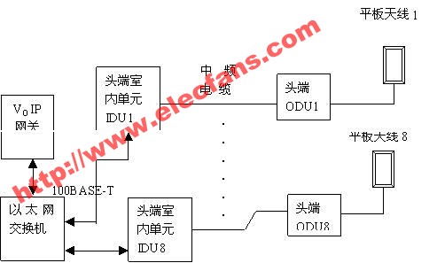
Second, the device configuration
The standard configuration of a central base station (HE) includes: central base station outdoor unit (RF), indoor unit (AP, intermediate frequency, control), VOIP gateway, Ethernet switch, router, network management (with QOS), UPS power supply, RF cable, IF cable and 45 ° sector flat panel antenna, etc.
The standard configuration products included in the cabinet of each 8-sector central base station are:
1. Eight indoor units (IDU). The network interface is an Ethernet interface, serving 8 sectors;
2. Outdoor unit (ODU), 8;
3. LCD monitor screen, one;
4. Network management system, 1 set;
5. Ethernet switch, 1 set;
6. Firewall, 1 set;
7. Stackable IP voice telephone gateway, 1 set;
8. Base station bandwidth management system (QOS), 1 set;
9. 5.8 GHz 45 ° sector flat antenna, 8 pairs;
10. Medium frequency low loss coaxial cable (50m), 8 pieces;
11. 8 RF cables;
12. Uninterruptible power supply system (UPS), 1 set;
13. Equipment Quick Installation Manual and User Manual, 1 set
3. Equipment configuration list
The list of sector center base station (HE) equipment configuration is as follows:
8 Sector Base Station (HE) Equipment Configuration List
No. Device Description Quantity Unit Remarks
1 Outdoor unit (RF) 8 SWR 5800AP (ODU)
2 Indoor units (AP, IF, control) 8 SWR 5800AP (IDU)
3 VOIP gateways 1
4 Ethernet switches 1
5 firewalls 1
6 network management system 1
7 LCD monitor screen 1
8 Base station bandwidth management system (QOS) 1
9 IF low-loss coaxial cable (50m) 8 50Ω, N-50J at both ends of the connector
10 RF cable (1.5m) 8 50Ω, N-50J at both ends of the connector
11 5.8 GHz 45 ° sector flat antenna 8 pay
12 19∥ cabinet (1.4 meters) 1 set
13 UPS power supply 1
14 1 set of other integrated materials, including waterproof kit, pole, etc.
Optional equipment:
1. Billing system;
2. Router.
4. Description
1. According to need, 8 sets of SWR5800 equipment can be expanded, of which 2 sets can be used to connect two central base stations.
2. If the system needs to be expanded in the future, only the central base station AP equipment needs to be added to each sector, and the system can be easily upgraded in the manner of polarization multiplexing or frequency multiplexing.
Multiple sets of SWR5800 devices can be multiplexed in one sector, and each sector can provide a transmission rate of N × 11Mbps or N × 54Mbps.
3. SWR5800AP can easily set the working frequency and output power, and temporarily change the sector planning and service area range that have been set before entering the field as needed to make the network achieve a better and stable effect.
Exhaust Fan, driven by the fan to rotate the air flow, so that indoor and outdoor air exchange of a class of air-conditioning appliances. Also known as ventilation fan. The purpose of the exhaust is to remove the indoor dirty air, adjust the temperature, humidity and sensory effects. Exhaust fans are widely used in homes and public places.
Exhaust fan, also known as negative pressure fan, negative pressure fan and so on. Is the use of air convection can make the room has been in a negative pressure state, the formation of a suction, a steady stream of outdoor air, and exhausted indoor hot air, so as to achieve ventilation and ventilation, cooling effect.
Exhaust Fan
8 Inch Exhaust Fan, Exhaust Fan For Bathroom, Exhaust Fan For Smoking Room, Exhaust Fan For Kitchen
Ningbo APG Machine(appliance)Co.,Ltd , http://www.apgelectrical.com