Design tasks and requirements
1.1 Design tasks and design requirements
This topic requires the development of a control software based on the Android (Android) mobile phone system, which will realize the remote control of the toy car with WIFI technology, including the car forward, backward, turn and other functions.
(1) Realize the connection between mobile phone and trolley WIFI;
(2) Real-time control of the car through the mobile phone.
1.2 Issues to consider when designing
a. Because the car end of the subject is received by the serial port communication, the mobile phone is a control command. Therefore, it is necessary to set the initial value of the MCU timer. If a common 12M crystal oscillator is used, the initial value is not necessarily an integer, and the communication will accumulate. The error, which in turn generates a baud rate error, affects the synchronization of the communication. A very accurate value can be obtained with a crystal of 11.0592M, so it is best to use a crystal of 11.0592M or an integral multiple thereof during the fabrication process.
b. When the motor of the car is started, the current is large, which may lower the voltage of the power supply instantaneously, which causes the MCU and the router to work normally. Therefore, a reliable power supply system must be designed.
c. Since all the source code of the Android system is public and can be used free of charge, each mobile phone company can change the code at will when developing its own products, and then there is a so-called "Android-based · · · improved system" mobile phone on the market. Mobile phone has different software compatibility for Android mobile phone software, so you must select the "Android original" mobile phone development software, we use the "Android 4.0" version of the operating system.
d. Since the current of the IO port of the MCU is mA level, the motor cannot be directly driven, and a special motor drive module must be designed.
2 overall system design
2.1 Scheme Argumentation
To realize the mobile phone through the WIFI control car, there are two ways to achieve: Solution 1: through the SIM card to achieve. The system block diagram is shown below:

Option 2: Implemented by a small router. The solution is to install a small router on the trolley side. It has a WIFI coverage around the car. Then the phone is connected to the router IP address, and the command is sent to it. After the router receives the command, it sends a data command to the serial port of the MCU to realize control. The system block diagram is as follows:
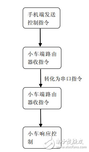
By comparing the above two options. Although the first solution can realize the ultra-long-range control of the trolley, the development cost is relatively high, which is technically difficult compared with the freshman, and the control process consumes the Internet traffic. The second option is relatively simple, and the development is less difficult. It is suitable for making toy cars, so we chose the second option.
2.2 Overall design block diagram
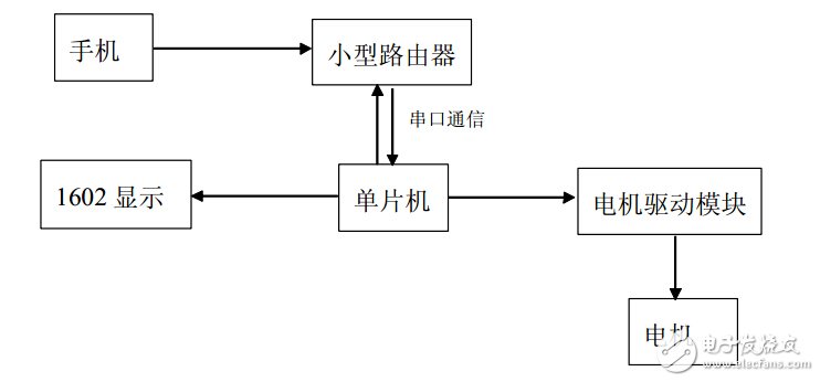
The general block diagram of the remote control car system is as follows
3 system hardware design
The hardware block diagram of the system is shown in the figure and consists of six parts. The six units will be described separately below.
3.1 Mobile phone design
3.2 Phone selection
Due to the rapid development of Android, the price of Android smartphones can now be reduced to less than 600 yuan, and Android-based application software is emerging one after another. Since all the source code of Android system is public and can be used free of charge, each mobile phone company can change the code at will when developing its own products, and then there is a so-called "Android-based · · · improved system" mobile phone on the market, source code The changes will affect the compatibility of the mobile phone to the Android software, and increase the development difficulty. Therefore, you must select the "Android original" mobile phone development software. We use the "Android 2.3.3" version of the operating system.
3.3 single chip circuit
3.3.1 Microcontroller selection
Here, the MCU needs to realize the control of the motor drive module, and also has a router for serial communication. In order to control the motor speed, it can be realized by using the timer of the MCU. The MCU is used to control the IO port to generate the PWM wave. Adjust the motor speed by adjusting the duty cycle.
In addition, the STC89C52 is designed and configured for an oscillation frequency of 0 Hz and can be set by software. In idle mode, the CPU suspends operation, while the RAM timer counter, serial port, and external interrupt system can continue to operate. The power-down mode freezes the oscillator and saves RAM data, stopping other functions of the chip until external interrupt activation or hardware reset. At the same time, the chip also has three package types: PDIP, TQFP and PLCC.
Should be different product needs.
The main features of the microcontroller:
• 8031 ​​CPU is compatible with MCS-51
• 8K bytes of programmable FLASH memory (lifetime: 1000 write/erase cycles)
• Full static operation: 0Hz-24KHz
• Three-level program memory security lock
• 128*8-bit internal RAM
• 32 programmable I/O lines
• Two 16-bit timer/counters
• 6 interrupt sources
• Programmable serial channel
• Low power idle and power down modes
• On-chip oscillator and clock circuit
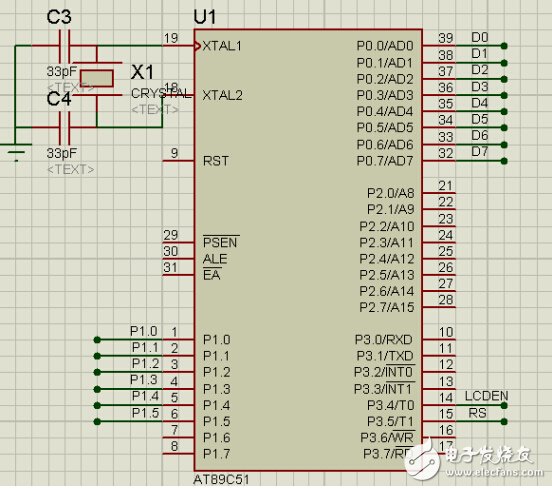
3.3.2 Crystal selection
Since the car end of the subject is received and received by the serial port communication, it is a control command. Therefore, it is necessary to set the initial value of the MCU timer. If a common 12M crystal oscillator is used, the initial value is not necessarily an integer, and the accumulated error will occur during communication. In turn, a baud rate error is generated, which affects the synchronization of the communication. A very accurate value can be obtained with a crystal of 11.0592M, so it is best to use a crystal of 11.0592M or an integral multiple thereof during the fabrication process.

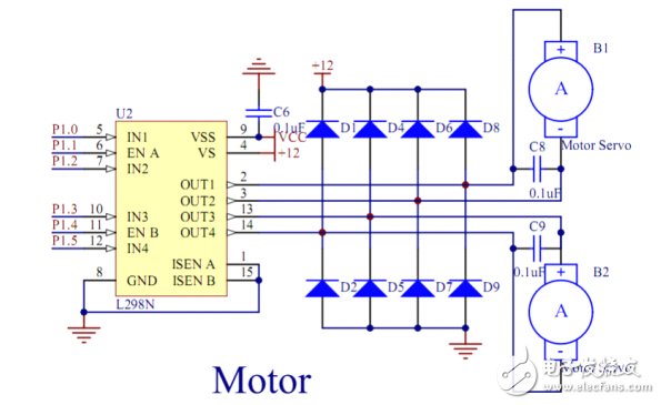
3.4 Motor drive module
Since the rated voltage of the chassis motor of the car is 12V, the motor drive module selects the common 12V motor drive chip L298N.
L298N constant voltage constant current bridge type 2A driver chip, L298N can accept standard TTL logic level signal VSS, VSS can be connected to 4. 5 to 7 V voltage. 4 feet VS connected to the power supply voltage, VS voltage range VIH is +2. 5 to 46 V. The output current is up to 2.5 A and can drive inductive loads. The emitters of the 1 and 15 foot tubes are separately led out to access the current sampling resistor to form a current sensing signal. L298 can drive 2 motors, and OUT1, OUT2 and OUT3, OUT4 can be connected separately.
3.5 motor
12V 138rpm DC motor
3.6 Power supply design
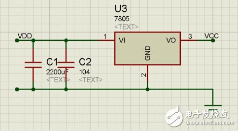
When the car motor starts up, the current is large, which may cause the voltage of the power supply to be pulled low instantaneously, which causes the MCU and the router to not work properly. Therefore, a reliable power supply system must be designed.
The following three methods are commonly used to solve this problem:
1) Select a power supply with better performance:
2), using independent power supply, that is, using two power supplies to supply power to the microcontroller and motor respectively;
3) Connect a larger value of capacitance in parallel with the power supply. When the motor starts, the current is large, and the electricity in the capacitor can compensate a part of the current to ensure that the voltage is not too low.
Editor's comment : The unique innovation of this project is that the control of the car is realized by the mobile phone, instead of the remote control handle or computer, so that it is more convenient to use, and realize the remote control of the toy car with WIFI technology, including the forward, backward and turn of the car. And other functions.
Electronic enthusiasts "Automotive Electronics Special", more quality content, download now 
The GFCI will not protect you from line contact hazards (i.e. a person holding two "hot" wires, a hot and a neutral wire in each hand, or contacting an overhead power line). However, it protects against the most common form of electrical shock hazard, the ground-fault. It also protects against fires, overheating, and destruction of wire insulation.
Ground Fault Circuit Interrupter UL
Ground Fault Circuit Interrupter UL,Auto-Monitoring Ground Fault Circuit Interrupters,Ground Fault Circuit Interrupter,Outlet Ground Fault Circuit Interrupter
Hoojet Electric Appliance Co.,Ltd , https://www.hoojetgfci.com