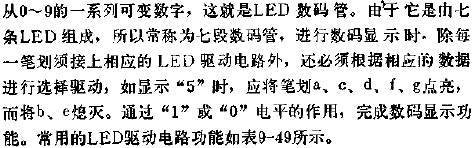
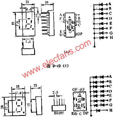
The LED digital tube connects the strip-shaped light-emitting diodes together and arranges them in the shape of "8" as shown in the figure, and the other end is taken as the control end respectively. If one of the strips is respectively turned on to emit light, it can be obtained.
This article refers to the address: http://

315mhz Antenna Description:
The head straight rod antenna it is to 315 MHZ wireless digital/special meter reading communication system design of the antenna.The antenna standing wave ratio performance is good, small dimension, structure, easy installation, stable performance, has the very good anti vibration and aging.
Features:
Frequency range: 315Mhz
VSWR:<1.5
Input impedance:50Ω
Maximum power input: 10W
Gain: 3dBi
Polarization: Vertical polarization
Weight: 10g
Lead wire:no
Antenna color: black
Interface form: SMA
Picture show:


315mhz Antenna
315mhz Antenna,315Mhz Rubber Antenna,Omni Directional Antenna,Short Rubber Antenna
Shenzhen Yetnorson Technology Co., Ltd. , http://www.yetnorson.com