I. Introduction
High-power high-brightness light-emitting diodes (LEDs) are a new type of cold light source that is the most promising in the 21st century. Its luminescence mechanism is based on the electrons in the PN junction transitioning between the energy bands to generate light energy. When it is under the action of an external electric field, the electrons and holes radiate together to generate an electric effect to convert a part of the energy into light energy without radiation. The lattice oscillation generated by the composite converts the remaining energy into heat. Since the spectrum does not contain infrared components, the heat generated cannot be radiated by radiation, so the LED is called a cold light source.
At present, the luminous efficiency of LED is only 10%~25%, and the rest of the energy is converted into thermal energy. If the heat in the LED chip cannot be dissipated in time, it will accelerate the aging of the device. Once the temperature of the LED exceeds the maximum critical temperature, the LED will always be permanently formed. Sexual failure. According to reports, the life of LEDs operating at 30 ° C is 20 times longer than that at 70 ° C. Therefore, heat dissipation technology is one of the key technologies for LED lamp design.
Heat exchange is carried out in three basic ways: heat conduction, convection heat transfer and radiation heat transfer. It can be divided into transient heat exchange and steady state heat exchange. In general, radiation heat transfer is not considered in engineering analysis. For continuous media, let a certain time t, the temperature field of all points in the object in the Cartesian coordinate system is t = f (x, y, z, t), the differential equation of heat conduction can be expressed as follows:
 (1)
(1)
Where Ï is the density, unit kg/m3; C is the specific heat capacity, unit J/(kg.K); λ is the thermal conductivity (thermal conductivity), the unit is W/(mK); φ is the internal heat source intensity, unit W /m3.
For continuous media, the energy differential equation for two-dimensional convective heat transfer is as follows:
 (2)
(2)
Where Cp is the specific pressure heat capacity, and for solid and incompressible fluids, Cp=C; u, v are the speeds in the x, y direction, respectively.
The matrix form of the above heat exchange is as follows:
 (3)
(3)
Where [C(T)] is the specific thermal matrix; [K(T)] is the conduction matrix, including the thermal conductivity and convection coefficients; {T} is the node temperature vector; {T } is the derivative of temperature versus time; [Q (T)] is the node heat flow vector.
Second, analysis project description
1. Lamp body description:
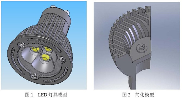
The analysis model is an LED lamp of a large company with a specification of φ48×38, three standard LEDs of 1W, and a mounting diameter of φ12 (uniform).
2. The lamp body model is simplified:
In order to save the cost of computer resources, from the symmetry of the luminaire, take a 1/3 model for simplified analysis (Figure 2), the package structure and component composition of a single LED are shown in Figure 3 and Figure 4:
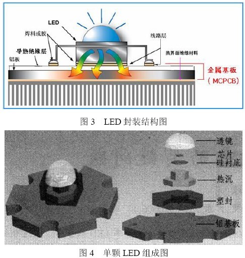
The simplified model includes: lamp body, aluminum substrate, heat sink and LED light-emitting chip. The plastic part of the LED package (which has a large thermal resistance), the lens, the substrate, and the thin wire can be omitted.
According to the literature, the heat of 1W single LED heat radiation is about 1.63% of the total heat. Only considering heat conduction and convection, changing the packing materials of different packages has little effect on the reduction of thermal conductivity temperature (even if a thermal conductivity is found). When the epoxy resin composition package of up to 7 W/mK is used, the temperature of the chip is not much lower than that of the epoxy resin package with a thermal conductivity of only 0.25 W/mK, and the temperature of the aluminum substrate is only decreased by 2.271 ° C. In fact, the transparent silicone encapsulants with a thermal conductivity of more than 7 W/mK are not reported in the literature. The LED chips are thermally conductive through silver paste and heat sink, and the heat sink and aluminum substrate and aluminum substrate and lamp cup are both Conductively bonded through silica gel, the components are tightly bonded, usually with a silica gel thickness of um. For ease of analysis, the effects of silver glue and silica gel can be ignored. LED heat sink materials are often silver plated copper. Considering the purity of copper and the influence of silver paste on thermal conductivity, the actual thermal conductivity is slightly lower than that of copper.
The thermal endurance of the LED chip is not more than 110 °C. Considering the safety margin (generally 10~15 °C), the PN junction temperature of the chip should not exceed 95 °C. In practical applications, in order to extend the service life of the LED, the junction temperature is generally controlled. Below 70 ° C, this value is often used as a reference threshold for thermal design, after which the lifetime is reduced by approximately half for every 10 ° C increase in temperature.
When building the finite element model, considering the meshing, the rounded corners, small holes and some small features that have little effect on the results are deleted.
3. Discussion of several key issues
(1) Light body material:
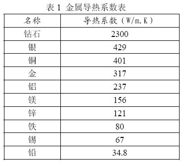
The choice of lamp body material mainly considers the thermal conductivity, price and processability of the material. The thermal conductivity indicates the thermal conductivity of the metal. The higher the thermal conductivity, the lower the thermal resistance and the higher the thermal conductivity. The thermal conductivity is usually determined experimentally. Among metal materials, diamond and silver have the highest thermal conductivity (see Table 1), but the cost is too high; pure copper is second, but processing is not easy. The LED heat-dissipating lamp shell is generally made of aluminum alloy 6063T5. This is because the aluminum alloy has good processability (pure aluminum is difficult to be cut due to insufficient hardness), surface treatment is easy, and the cost is low. Usually, it is die-casting or extrusion molding. The thermal conductivity is about 1/2 of that of pure aluminum. With the increase of temperature, the thermal conductivity of aluminum alloy increases. The thermal conductivity of aluminum alloy changes with temperature.
(2) Air convection coefficient:
The heat exchange process is widely present in other phenomena such as natural or forced convection flow in the tube, gas plunging plates, and the like. Since the computational correlation of heat exchange is difficult to give more accurate calculation results, and it is easy to make mistakes when using, we usually recommend some empirical data. The empirical formula for the air convection coefficient is as follows:
Inner surface: h = 2.5 +4.2v (4)
Outer surface: h = (2.5 ~ 6.0) + 4.2v (5)
Where h is the air convection coefficient and v is the air flow rate.
A 0.2m2 horizontally placed flat plate has a convective heat transfer coefficient with air of about 5W/m2K under natural convection and a convective heat transfer coefficient of about 15W with forced convection at an air flow rate of 3m/s. m2K, considering that the LED lamp is mostly used in indoor enclosed environment, the external convection coefficient of the lamp is taken as 5W/m2K, the internal convection environment of the lamp is taken as 2.5W/m2K, and the ambient temperature of the lamp taken during CAE analysis is room temperature 25°C. .
(3) Calorific value:
The heat dissipation problem is a key issue that needs to be solved by the power LED. The quality of the heat dissipation is directly related to the reliability of the device. As we all know, increasing the input power of the LED, the brightness of the LED will be proportionally enhanced, but since the efficiency of the LED is far below 100%, the current power LED can only convert a small amount of electrical energy into light energy, and the remaining 80% of the energy is converted into heat energy. Considering the power supply heating, radiation heat transfer and other energy exchanges, the comprehensive experimental test data can be taken as 80% of the nominal power of the LED. The heat generated in this model is about 0.8W. The size is 1×1×0.25mm, and the heat generation rate is 3.2W/mm3. In order to simulate the uniform heating of the chip, the thermal resistance of the chip is taken to be a small value.