Abstract: Maxim's Gigabit (Gigabit) Multimedia Serial Link (GMSL) scheme can serially convert digital video and audio data, and then serially transmit it through a pair of twisted pairs. In addition, the integrated bidirectional control channel enables a single microprocessor (µC) to program the serializer, deserializer, and all connected peripherals. In typical applications, the remote microprocessor and related devices such as clock source / crystal and low-voltage power supply can be omitted. This solution not only simplifies the remote design, but also reduces system cost, size and power consumption. However, in some cases, considering the special requirements beyond GMSL, µC still resides at both ends of the link in the system. This application note describes how to connect two µCs to control GMSL.
Double µC application foundation
When using a single µC, if µC is on the serializer side, the control direction selection pins (CDS) at both ends of the serializer / deserializer are usually set to low level; if µC is on the deserializer side, the direction is controlled Select to set high. However, if the CDS of the serializer is set low and the CDS of the deserializer is set high, each GMSL chip can be simultaneously connected to its corresponding µC (Figure 1).
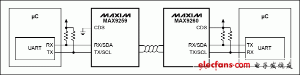
Figure 1. Simple dual µC application schematic with CDS settings as shown
Internal operation
When two µCs are used, both the serializer and deserializer I²C host are disabled, and RX / SDA and TX / SDL are configured as UART interfaces by their corresponding µCs. Since each device operates as a local device, it cannot enter the sleep state. Use the corresponding low-level active PWDN pin to control each device to enter a low-power state. Keep in mind that when awakening from a power-off state, all device settings are reset to their initial power-up values.
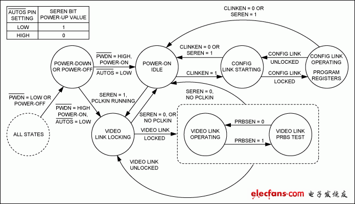
Figure 2. Serializer state diagram (CDS = low level)
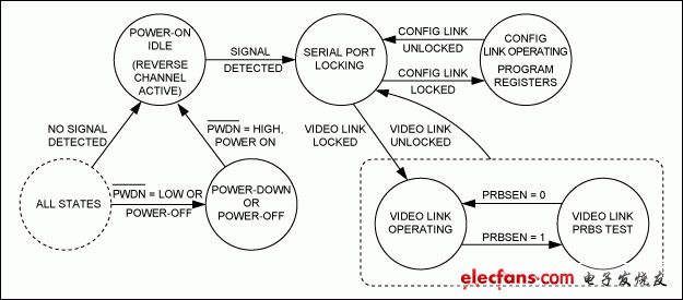
Figure 3. Deserializer state diagram (CDS = high level)
Philippines Power Plug,Philippines Power Outlet,Philippines Electrical Outlet,Philippines Electric Socket
Heikki Technology Co., Ltd. , https://www.heikkipower.com