The use of electromagnetic induction and reactor principle, professional development, the use of high-performance filter capacitors series high linearity filter device, combined into a filter compensation system, in the absorption of the main harmonic components of the system, while compensating for reactive power, quickly follow Load changes have the effect of suppressing current fluctuations, absorbing harmonics in the power grid and improving the efficiency of electrical energy utilization.
The HFR harmonic filter helps to relieve the overload caused by the load harmonic current and the overheating of the power infrastructure, so that the power system can be fully utilized. Smaller harmonic currents reduce system resonance and potential outage risks of sensitive electronics.
Product Features: Designed to substantially eliminate harmonic current distortion caused by pulse rectifiers.
The Howcore series of harmonic filters is a passive series of low-pass filtered, inductor-capacitor systems designed to eliminate the unique 5, 7, 11 and 13 low frequency harmonics generated by three-phase full-wave variable-frequency loads. No single adjustment or phase shift by different harmonic sources is required. Harmonic content can be controlled up to 8%.
Features:
1. Extend the life of electrical equipment such as transformers, cables, motors, etc., and increase the reliability of electrical devices.
2. Stable performance, high reliability, and low maintenance cost contribute to energy conservation and emission reduction.
Howcore harmonic filter efficiency exceeds 98%, power can reach 250kw, cost-effective, durable.
In addition, the Howcore harmonic filter neither causes resonance in the power system nor absorbs harmonics from other non-linear loads.
3. Suitable for project modification applications where the position adjustment of the frequency converter is limited.
Hongkang HFR harmonic filter adopts plug-and-play method, its structure is more compact than similar products, it is easy to install quickly, and it is convenient for debugging.
4. It can be directly used together with the DC reactor, EMC/EMI filter, etc. that have been installed.
5. The standard motor drive can be quickly and easily upgraded to low harmonic drive.
Harmonic filters are commonly used in three-phase electronic devices such as variable speed AC and DC motor drives, welding machines, battery chargers, uninterruptible power supplies (UPS), induction heating devices, servo drives, and other electronic devices. Applicable to paper, tires, chemical fiber, prevention, petrochemical ... and other industries
Linear load:
When a sinusoidal voltage V is applied to a resistor R in a purely resistive load, such as an incandescent bulb, the current I, which is also sinusoidal, has the same phase as the voltage V.
The power consumed by the load is: P=U×I
For reactive loads (such as induction motors), although the current is no longer in phase with the voltage, it lags behind the voltage, producing a hysteresis active power factor of less than 1. In the case of capacitive loads, the current is earlier than the voltage and produces a leading active power factor of less than one.
In this case, AC power includes three components: active power (P), reactive power (Q), and apparent power (S).
The apparent power is: S = U x I (where S = [kVA], P = [kW], and Q = [kVAR])
In the case of a perfectly sinusoidal waveform, P, Q, and S can be represented as a vector that forms a triangle: S 2 = P 2+ Q 2
The displacement angle between current and voltage is φ. Displacement power factor is the ratio between active power (P) and apparent power (S): DPF = PS = COS (φ)
Nonlinear loads
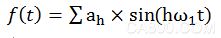
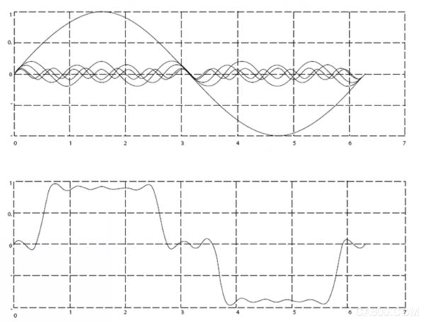
Non-linear loads such as diode rectifiers have non-sinusoidal currents. The non-sinusoidal waveform can be decomposed into the sum of a sinusoidal fundamental wave and a harmonic wave, which is an integral multiple of the fundamental wave.
In non-linear systems, between the effective power factor and the displacement power factor
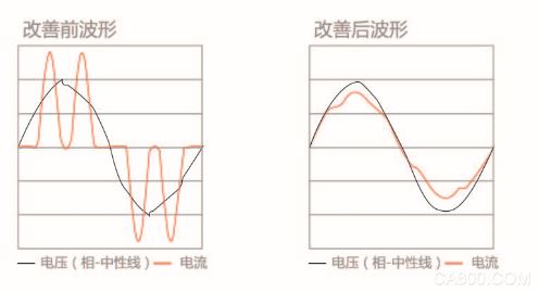
The following figure shows the current after 6-pulse rectification on a three-phase power supply.
In a nonlinear system, the relationship between the effective power factor and the displacement power factor is:
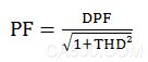
The power factor decreases with reactive power and harmonic loads. A low power factor increases RMS current and increases losses in the supply cable and transformer.
Harmonic side effects are two parts
Harmonic currents cause system losses (layout cables, transformers)
Harmonic voltage distortion interferes with other loads and increases the loss of other loads
Harmonic limit requirements
· Application-specific requirements
· Standard requirements that must be complied with
The requirements for a particular application are related to the specific installation in the presence of limiting harmonics technology.
For example, on a 250kVA transformer connected to two 110kW motors. One direct connection, one via inverter. If the direct connection motor also needs to be powered by a frequency converter, in this case, the size of the transformer is small. To improve without replacing the transformer, an AHF filter must be used to reduce the harmonic distortion caused by the two frequency converters.
There are various harmonic improvement standards, regulations and recommendations. Different standards apply to different regions and industries. The following are the criteria that will be encountered:
· IEC/EN 61000-3-2
· IEC/EN 61000-3-12
· IEC/EN 61000-3-4
· IEC 61000-2-2
· IEC 61000-2-4
· IEEE 519
· G5/4
IEC 61000-3-2, Harmonic current emission limits (equipment input ≤ 16A per phase).
The scope of IEC 61000-3-2 is for equipment connected to a public low-voltage power distribution system (with an input current of 16A or less per phase). The four categories are defined as follows: Class A to Class D.
IEC 61000-3-12, Harmonic current limits generated by common systems connected to input currents >16A and ≤75A.
The scope of IEC 61000-3-12 is a device connected to a public low voltage distribution system with an input current between 16A and 75A. Current emission limits are limited to 230/400V 50Hz systems, and will increase the limits of other systems in the future. Includes harmonics (5th, 7th, 11th, and 13th) and THD and PWHD requirements. The Automation Drive range (FC 102 HVAC, FC 202 Aqua, and FC 302 Industry) drives meet these limits without additional filters.
IEC 61000-3-4, Limits, Harmonic Current Limits for Equipment in Low-Voltage Power Systems with Current Ratings Greater than 16 A When the current is less than 75 A, IEC 61000-3-12 is better than IEC 61000-3-4.
Therefore, IEC 61000-3-4 applies to equipment with a current rating greater than 75A connected to a public low voltage distribution system. As part of the technical report, it should not be regarded as an international standard. The three-level evaluation process applies to the connection of the equipment to the public power supply. According to the specified power of the load, the equipment above 75A is limited to the level 3 connection. The power supply department can accept the connection of the equipment based on the load to install a given effective power, according to the requirements of the local power supply department. Manufacturers should provide values ​​for each harmonic of THD and PWHD.
IEC 61000-2-2 and IEC 61000-2-4 low-frequency conducted disturbance compatibility levels.
IEC 61000-2-2 and IEC 61000-2-4 electromagnetic compatibility environments 2-2, 2-4: Compatibility levels for low-frequency conducted disturbances and signal transmissions in public low-voltage power supply systems. 2-2 is a public low-voltage power supply system, and 2-4 is an industrial facility.
IEEE 519, IEEE Practice and Harmonic Control Requirements in Power Systems.
IEEE 519 established the goal of electrical system design including linear and non-linear loads. Determine the waveform distortion target and determine the point of common coupling (PCC) between the power supply and the load.
The IEEE 519 is a system standard designed to control the voltage distortion rate at the PCC point to 5% THD and limit the maximum frequency voltage harmonics to 3%. Harmonic current limit development was designed to limit the harmonic injections of individual users so that there would be no unacceptable level of voltage distortion and limitations beyond the total harmonic distortion of the system voltage supplied by the electrical equipment.
The current distortion limit, as shown in Table 10.3 in the standard, depends on the ISC/IL ratio, where ISC is the short-circuit current at the point where the consumer PCC is located and IL is the maximum demand load current. These limits apply to single harmonics (up to the 35th) and total demand distortion (TDD). Please note that these limits apply at the point of use of the PCC. When required, individual loads that meet these limits also ensure PCC point compliance, which is the most economical solution. The most effective way to meet the requirements of harmonic distortion is to improve on the incoming side of each load and measure at the PCC point.
However, if the frequency converter is required to comply with the IEEE 519 current distortion limit in a given application, then these limits can be met using AHF.
G5/4, Guidelines for Engineering, UK Harmonic Voltage Distortion and Planning Values ​​for Nonlinear Equipment Access to Power Transmission Systems and Distribution Networks.
G5/4 specifies the planned value of harmonic voltage distortion used in the non-linear equipment access process. The process of determining each user's emission limits based on these planning values ​​is described. G5/4 is a system-level standard.
The THD planning value is 5% for 400V rated points. The evaluation process for non-linear device access is described. This process follows a three-level evaluation procedure designed to balance the level of unacceptable voltage harmonic distortion risk caused by the level of detail required in the evaluation process with the connection of some devices.
System compliance with frequency converters depends on the specific topology and distribution of nonlinear loads. Use of AHF meets G5/4 requirements.
Harmonic improvement
To improve the harmonics produced by the 6-pulse rectifiers of the frequency converter, there are several solutions and each has its own advantages and disadvantages. The choice of the right solution depends on the following factors:
· Grid (background distortion, mains imbalance, resonance and supply type - transformer/generator)
Applications (load distribution, load capacity and load size)
· Local/National Standards/Regulations (IEEE 519, IEC, G5/4, etc.)
· Total cost (initial cost, performance, maintenance, etc.)
The IE standards of different countries (regions) or transnational organizations are the same. All of the above IEC standards are consistent with the EU standard with the prefix "EN". For example, the European Union EN 61000-3-2 is identical to IEC 61000-3-2. This situation is similar to the situation with the prefix AS/NZS Australia and New Zealand.
There are two main types of harmonic solutions: passive and active.
Among them, passive solutions include capacitors, reactors, or two different combinations of devices.
The simplest solution is to install a 3% to 5% reactor on the input side of the inverter. This inductor reduces the amount of harmonic current generated by the frequency converter. More advanced passive solutions consist of capacitors and inductors to reduce the harmonics from such as the 5th and above.
The active solution is an active shunt filter that monitors the line currents of all three phases and processes the measured current signal through a digital signal processing system. The filter then actively applies an inverted phase signal to the unwanted components of the current to perform the compensation operation. Active solutions can improve real-time harmonic interference to make this solution very effective in any load distribution. For more information on active solutions Low Harmonic Drive (LHD) or Active Filter (AAF), see MG.34.OX.YY and MG.90.VX.YY.
working principle
The Advanced Harmonic Filter (AHF) includes a secondary absorption circuit that combines a primary inductor L0 and inductors L1 and L2 and capacitors C1 and C2. The absorption circuit is specially tuned to improve the harmonic currents at the 5th and 5th times. The fundamental frequency of 50Hz and the fundamental frequency of 60Hz are different fundamental frequencies.
Filter performance varies with load function. At rated load, the performance of the AHF010 filter is equal to or better than 10% (THiD).
THiD has higher values ​​under partial load conditions. However, even if the THiD has a higher value, the absolute value of the harmonic current is lower at the part load. Therefore, the side effects of harmonics under partial load conditions are lower than those of harmonics under full load conditions.
Capacitor disconnected
If the application requires a high power factor in the no-load condition and needs to reduce the capacitor current in the standby condition, the capacitor connection should be disconnected. The contactor can disconnect the capacitor when the load is less than 20%.
It is also very important to consider the capacitive current in the design of the harmonic filter when the generator is powered. Capacitive currents can over-excite the generator under no-load and low-load conditions. Excitation can cause the voltage to rise above the allowable voltage of the AHF and the frequency converter. Therefore, be sure to disconnect the capacitors and seriously consider the design in generator applications.
In terms of background distortion and power supply imbalance, passive harmonic filter performance (such as AHF) is superior to multi-pulse rectifiers. However, considering the partial load and power factor applications, the passive filter performance is worse than the active harmonic filter. For the performance positioning of the various harmonic improvement solutions provided, please refer to the relevant harmonic improvement data.
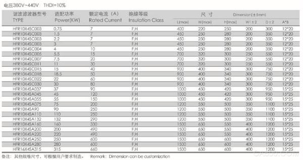
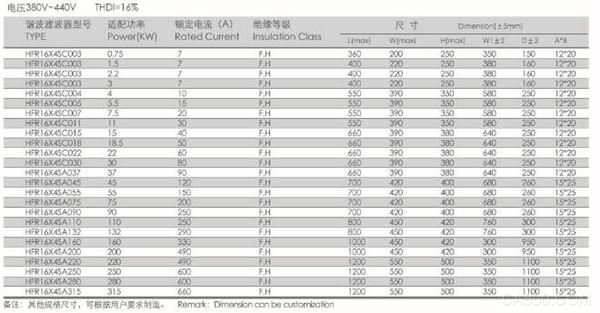
Technical specifications
· Working voltage: 220VAC-690VAC
· Working current: 20A-660A
· Operating frequency: 50/60Hz
· AC pulse voltage: It is required to sustain AC pulse voltage of ±2500V
· Insulation class: class F,H
· Current total harmonic distortion rate THDi ≤ 8%
· Total harmonic distortion THDv ≤ 5%
· Fundamental loss ≤10%
· Operating environment: -10...+45 °C, rating will not decrease. Up to +55°C, above 45°C,
1% reduction in rated current per 1°C increase
· Protection level: IP00-IP22
· Maximum current: 1.5× rated current, continuous 60S
· Noise: ≤65dB
· Temperature rise: ≤70K
· Anti-electrical strength: No arcing breakdown of core-winding 3000VAC/50Hz/5mA/10s (factory test)
Insulation resistance: 1000VDC insulation resistance ≥100MΩ
· The altitude does not exceed 2000 meters.
· Operating environment temperature -25 °C ~ +45 °C, relative humidity does not exceed 90%.
· No harmful gas around, no flammable or explosive materials.
· The surrounding environment should have good ventilation conditions. If it is installed in the cabinet, ventilation equipment should be installed.
Typical circuit diagram

typical application
· Equipment with front-end six-pulse rectifier
AC and DC motor drivers
· Factory automation equipment
· UPS and three-phase power
· Water/wastewater treatment facilities
· Oil and gas exploration
· Heavy industry and machinery
· Self-contained systems (such as ships)
· Fan and Pump Applications
· battery charger
· Heat ventilation and air conditioning engineering installations
· Key Projects
Remarks: Applicable to all kinds of power equipment with front-end six-pulse rectification.
Reduce the harmonic current below the specified value.
Daily electricity load, a large part of non-linear load.
HFR harmonic filters can quickly and easily upgrade standard motor drives to low harmonic drive.
Under no-load conditions (inverter in stand-by mode), the inverter current is negligible and the main current generated by the grid is the current through the capacitor in the harmonic filter. Therefore, the power factor is close to 0 and it is capacitive. The capacitor current is approximately 25% of the filter's rated current (depending on the filter size, typical values ​​between 20% and 25%). The power factor increases as the load increases.
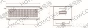
Product Size
Shanghai Hongkang Electric Co., Ltd.
phone
Http://
1500 Puff Vape,Electronic Cigarette Oem,1500 Puff Cigarette,1500 Puffs Disposable Vape
ALD GROUP LIMITED , https://www.aldvapor.com