0 Preface
LED lighting has obvious advantages such as energy saving, environmental protection and long life. With the decline of prices, the popularization speed has accelerated significantly in recent years. At the same time, LED lighting control technology has also developed rapidly. The new LED control system uses a combination of microcontrollers, wireless communications, sensors and other technical means to achieve multi-parameter, intelligent, and scene lighting control, which can create an artistic atmosphere of light, bring people enjoy, and maximize Improve the utilization of electric energy to achieve the effect of energy saving and consumption reduction [1~7]. Due to cost and other reasons, the current LED lighting control system is mainly used for outdoor public lighting, landscape lighting, stage lighting control and other occasions [8~9], household LED is basically based on functional lighting, most of which still use traditional simplicity. Switch control, light intensity and color temperature are basically fixed, it is difficult to meet the personalized, artistic lighting needs of home users.
The LED lighting control system designed in this paper uses a cost-effective microcontroller, constant current driver and wireless transceiver. It uses PWM dimming and RGB color mixing technology to produce different light intensity and color temperature effects. It has good controllability and flexible configuration. The advantages of lower cost, etc., can meet the basic needs of home LED scene lighting, and have positive significance for promoting the popularization of household LED lighting.
1 Overall structure
The LED lighting control system consists of a wireless remote control and multiple LED dimmers, all using a microcontroller-based hardware architecture, as shown in Figure 1. Both devices communicate via a wireless transceiver, and the communication protocol is a custom type. The user uses the human-computer interaction interface provided by the remote controller to set the desired lighting scene and sends it to the dimmer in the form of an instruction packet. After receiving the command, the dimmer adjusts the PWM duty ratio of the R, G, and B3 LED drivers in real time, and accordingly changes the power ratio of the red, green, and blue LED lights, and generates the desired light intensity by mixing colors. Color temperature effect [10~14]. The scene memory is used to store multiple sets of scene data, and the user uses the scene number as an index to complete the scene creation and editing operations by using the remote controller interactive interface.
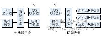
Figure 1 System structure diagram
Microcontroller selection is the basis for system hardware design. In order to ensure the smoothness of LED dimming, the microcontroller is required to have three hardware PWM output ports, which are driven by the same clock source. In addition, in order to improve the efficiency of the remote control battery, the microcontroller is required to support the nanowatt sleep mode and can be quickly woken up by the button. Combined with hardware versatility, development methods, supply, cost performance and other factors, decided to use STC12LE5410AD as the main controller of the remote control and dimmer. STC12LE5410AD is a single clock/machine cycle microcontroller of 80C51 core. Under the same crystal condition, the working speed is 8~12 times faster than that of ordinary 80C51 chip.
Wireless transceivers have different modulation types such as ASK, FSK, PSK, and some also support standard wireless network protocols, such as IEEE802.15.4, Wi-Fi, ZigBee, and Bluetooth protocols, which can be selected according to specific application requirements. For smaller LED wireless control systems, a non-standard protocol chip with high cost performance can be used. nRF24L01+ is a low-power 2.4GHz ISM band wireless transceiver chip introduced by NORDIC. It adopts GFSK modulation mode, supports 126 communication channels and up to 2Mbps air transmission rate. Built-in EnhancedShockBurst data link layer protocol can automatically complete package unpacking and address discrimination. , CRC check, response, retransmission, etc., effectively reduce the main processor load [15]. The performance of the nRF24L01+ has been verified in products such as wireless keyboards and wireless mice.
2 hardware circuit
Figure 2 shows the specific circuit of the wireless remote controller. The STC12LE5410AD operates at 12MHz and is powered by a 3V battery. It supports external RC, internal low-voltage detection and various reset modes of the watchdog. The TFTLCD module with SPI interface is displayed with a resolution of 320×240. The LCD module comes with an SD card interface. In addition to the scene table, the Chinese character library required for LCD display is also stored in the SD card. Buttons K1~K7 are used for interactive input, and the connected port lines support interrupt wake-up function. nRF24L01+ adopts SPI control interface, and has two separate contact lines of CE and IRQ. CE is used for working mode control (cooperating with related register control bits), and IRQ is used for transmitting and receiving status indication.
STIC12LE5410AD SPI signal lines MOSI, MISO, SCK are shared by nRF24L01+, LCD, SD card, port lines P11, P12, P13 are used for independent chip selection of three, P32 is IRQ interrupt input port of nRF24L01+, P10 control buzzer P22, P23, P21 control LCD reset, data/command channel selection and backlight.
Figure 3 shows the hardware circuit of the dimmer. The wireless transceiver part is the same as the remote control, so it is omitted. The STC12LE5410AD has four programmable counter array (PCA) modules based on the same clock source. It can be used for software timer, input pulse capture, square wave output or PWM output. Here, the corresponding P37, P35 and P20 are used as 3-way LED drivers. PWM control port (only one way is drawn in the figure). The LT3756 is a new high-power LED driver chip with an input voltage of 6~100V and an external N-channel MOS-FET. It can drive 20 1A white LEDs under 12V input conditions with an efficiency of over 94% and a frequency range of 100kHz~1MHz. The LT3756 features TrueColorPWM dimming technology with a dimming range of 3000:1. In order to facilitate the debugging of the PWM function of the LED driver, five buttons are designed in the circuit, which can also be used for manual adjustment of the lighting scene during system operation.
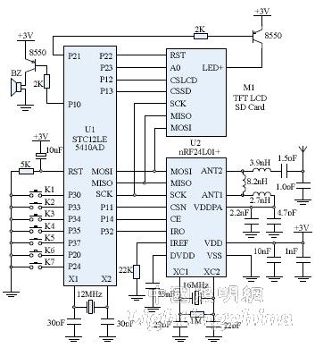
Figure 2 Remote control hardware schematic
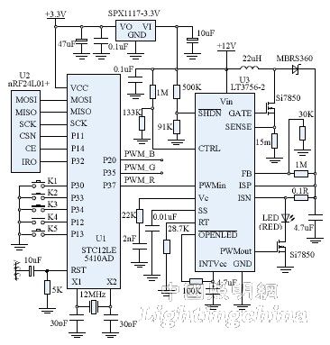
Figure 3 Dimmer hardware schematic
3 software design
The software flow of the remote control is shown in Figure 4. After power-on/reset and after performing initialization-related operations, the STC12LE5410AD goes to sleep. After any button is pressed, the STC12LE5410AD is awakened, and then performs tasks such as man-machine conversation, information access, and data transmission, and then goes to sleep again. With this low duty cycle mode, the average operating current of the remote control can be reduced to less than 1uA, significantly extending battery life.
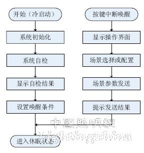
Figure 4 remote control software flow chart
The man-machine dialogue process includes tasks such as interface display, scene selection, scene configuration, and effect preview. In order to achieve friendly, convenient, and WYSIWYG interaction effects, the menu structure, screen display, switching mode, and input response design must be people-oriented. Fully take care of the psychological and operational habits of the average user, and continue to optimize according to user feedback [16].
Figure 5 shows the format of the nRF24L01+ packet. The preamble and CRC are used for receiving synchronization and packet verification respectively. The packet control field is composed of the payload (here, scene data) byte number, packet identifier and ACK response enable bit, and the dimmer ID is used to distinguish the remote control. Object. The first 3 bytes of the scene data are RGB ratio, and the last 2 bytes are timing parameters, where 0x0000 means to turn off the LED immediately, 0xFFFF means that the scene illumination is immediately enabled, until the next time the LED is turned off, other values ​​indicate scene illumination immediately. Enable, delay the value of the corresponding length (in minutes) and automatically turn off the LED.
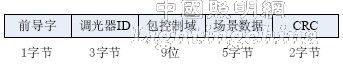
Figure 5 Wireless transmission packet format
Figure 6 shows the software flow of the dimmer. After the dimmer is powered on/reset, perform initialization-related operations and then turn off the LED (scene reset). Once the scene data sent by the remote controller is received and confirmed to be valid, the light intensity, color temperature and timing effect specified by the new scene are generated.
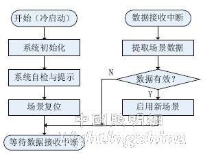
Figure 6 dimmer software flow chart
The software development environment of the remote control and dimmer is KeilC51, and the programming uses C language. The final generated HEX code file is downloaded to the STC12LE5410AD program memory by using STC_ISP programming tool and serial data cable.
4 Conclusion
The LED lighting control system designed in this paper has achieved the unity of practical and artistic LED lighting, stable system operation and friendly man-machine interface. Compared with the LED control system using DALI, DMX512, ZigBee, GPRS and other wired or wireless protocols, the cost performance advantage is obvious, and it has high promotion value in the field of household LED lighting.
The intelligent and scene control of LED lighting meets the diversified, personalized and artistic consumption needs of household lighting, and reflects the people-oriented development concept. In addition, the on-demand allocation of lighting resources can also help improve energy efficiency, reduce energy waste, improve the relationship between people and the environment, and have positive significance for building a low-carbon society.
Edit: Cedar
Molded Case Circuit Breaker,Ir Windows For Switchgear,Automatic Transfer Switchgear,Eaton 15Kv Switchgear
Shandong Shunkai electrical equipment co., LTD. , https://www.chinasdsk.com