The Internet of Things (IoT) refers to the deployment of various information sensing devices with certain sensing, computing, and execution capabilities in the physical world. The information is transmitted, coordinated, and processed through network facilities to achieve wide-area. Or a wider range of information exchange and exchange between people and things, things and things. Its purpose is to realize the connection between objects and objects, objects and people, all items and networks, and to facilitate identification, management and control. Internet of Things technology has broad application prospects in the fields of national defense, industry, urban management, public security, telemedicine, intelligent transportation, smart home, smart grid, environmental monitoring and green agriculture. Under the current situation of vigorously promoting energy conservation and emission reduction and delaying global warming, the Internet of Things provides the basis and key technologies for the integration of “management and control operations†in a harmonious society that achieves “high efficiency, energy conservation, safety and environmental protectionâ€. The technology is believed to set off the third wave of the information revolution. In the architecture of the Internet of Things, this paper attempts to discuss the related concepts with the indoor environment as the scene, gives the application model, analyzes the practical key technologies such as data perception, processing and comfort monitoring, and conducts experiments and makes Exploratory conclusions.
1 Related research
The concept of the Internet of Things should first be proposed by Professor ASHTON K, director of the Auto-ID Center for RFID research at the Massachusetts Institute of Technology in 1999. Various government departments have conducted extensive research on IoT-related technologies and industries and formulated a series of development plans.
In July 2011, the Ministry of Science and Technology of China issued the “National “Twelfth Five-Year Plan†for Science and Technology Developmentâ€, integrating the Internet of Things as a new generation of information technology into a strategic emerging industry with key developments in the country, and including the Internet of Things. The new generation of broadband mobile wireless communication network is among the major national science and technology projects. However, the existing research results are mainly concentrated in the fields of industry, transportation, security, etc. There are few studies on indoor Internet of Things for smart home and factory environment monitoring.
In recent years, the emergence of cloud computing technology, allowing users to access various computing resources, such as computing power, storage capacity, applications, services, etc., through the Internet, provides support for the development of the Internet of Things. At the same time, people are increasingly coming to the home indoor environment. The more attention, the quality of indoor environment directly affects the quality of human life, and even the survival of human beings. References discuss the relationship between indoor environmental parameters (temperature, relative humidity, acoustic environment, and light environment) and indoor environmental comfort.
2 system model design
In the initial stage of the development of the Internet of Things, its standard architecture is generally three layers: the perception layer, the network layer and the application layer, but the data generated, analyzed, processed and managed by the Internet of Things is massive, and the original data must have various actualities. Meaning, need to be supported by a huge amount of scalable computing resources. Cloud computing can provide flexible, infinitely scalable, and inexpensive computing and storage services to meet the needs of the Internet of Things. Therefore, this paper adds cloud computing to the IoT architecture to provide powerful computing power and computing intelligence services for IoT business needs. , constitute an improved online monitoring model of the home indoor environment including the sensing layer, the network layer, the cloud service layer and the application layer 4, as shown in FIG. 1 .

The sensing layer includes a data acquisition terminal device such as a sensor and a sensor network in front of the data input gateway. In the model, this layer is a wireless sensor network based on the ZigBee protocol; the network layer is mainly responsible for network access, network transmission, and corresponding management and control. The layer consists of the Internet, the remote intelligent monitoring platform and the network access program of the server cluster; the cloud service layer is mainly responsible for storing, mining, and analyzing the existing data, providing timely, scalable, and intelligent services for the application layer to ensure the application layer. Reliability, security, and scalability, can provide storage, query, analysis, mining, understanding and basic services based on sensing data decision and behavior according to needs; application layer solves information processing and human-computer interaction on system requirements The problem is to use the home indoor environment as the application scenario of the Web application service system to monitor the indoor environment and terminal equipment, and to adjust, analyze and predict the environmental status.
3 system platform design
3.1 Wireless Sensor Network
The wireless sensor network hardware platform in this system selects the wireless communication chip CC2530 development platform of American TI Company, and uses ZigBee protocol stack ZStack-CC2530-2.3.0- 1.4.0 and embedded development integrated environment (IDE) IAR Embedded Workbench for development. And manage wireless sensor network application engineering.
3.1.1 Network Structure
The wireless sensor network part included in the model adopts a star topology based on ZigBee technology. It consists of a master coordinator and multiple terminal nodes. The terminal node can only communicate with the corresponding master coordinator, and the terminal nodes cannot communicate with each other. The star topology has the advantages of simple network structure and low energy consumption of terminal nodes. The main coordinator and terminal nodes can have longer working hours under battery power supply.
ZigBee is a technical standard for networking, security and application software developed based on the IEEE802.15.4 wireless standard. It is characterized by close range, low complexity, self-organization, low power consumption, low data rate and low cost. TI's CC2530 chip integrates 51 MCU cores, and its development platform has a development template based on the 2004/2006/2007/PRO protocol stack. The ZigBee development platform for the CC2530 chip can be seamlessly connected to the IAR for MCS-51 integrated development environment for easy operation and connection. The main coordinator in the system is responsible for starting the whole network, and is directly powered by the USB interface; the terminal node is powered by the self-contained battery; the main coordinator and the remote intelligent monitoring platform are connected through the USB direct serial port, and the wireless device of the CC2530 realizes the wireless with the terminal device. Communication.
3.1.2 CC2530 Development Platform
The TI CC2530 development platform uses the Z-Stack micro operating system for application development. Z-Stack is an industry-leading ZigBee protocol stack from TI that supports multiple platforms. Z-Stack contains a nearly full-featured protocol stack of the mesh network topology. It is built using the idea of ​​the operating system. The event round-robin mechanism is used. When the layers are initialized, the system enters a low-power mode; when an event occurs. , wake up the system, start to enter the interrupt processing event, and continue to enter the low power mode after the end. If several events occur at the same time, the priority is judged and the events are processed one by one. This software architecture can greatly reduce system power consumption. The main workflow of the entire Z-Stack is roughly divided into system startup, driver initialization, OSAL initialization and startup, and entering the task rotation cycle.
In this system, due to the small number of sensing nodes and short transmission distance, the topology of the star network is selected, the coordinator uses the broadcast method to transmit information, and the terminal node uses the unicast transmission mode data. The CC2530 platform supports collision avoidance carrier sense multiple access (CSMA/CA) function. After the wireless sensor network is started, the primary coordinator is in the listening state, the terminal node transmits data, and if the listening channel state is idle, the data is transmitted. Packet, otherwise wait and delay until the channel state idle packet is sent successfully. The internal program flow of the terminal node in the wireless sensor network is shown in Figure 2.

3.2 Remote Intelligent Monitoring Platform
The remote intelligent monitoring platform that implements communication with the master coordinator in the wireless sensor network in this system is a Web system. The connection program is written in Java under the MyEclipse2013 environment, and the RXTXcomm.jar function library supports serial communication. The page program is implemented by JSP, which can adjust the baud rate and COM port, and can be remotely monitored. The platform implements data reception on the wireless sensor network, and collects data according to the set data format, and stores the program written in Java into the database of the remote server. The interface program flow is shown in Figure 3.
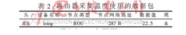
The system standardizes the data packets of each node through a structure to facilitate data collection. The packet format is shown in Table 1. The data header uses the "&&" character, and the data end uses 1 "&".

For example, when the routing node collects temperature, the following method of filling data is used, as shown in Table 2. The device name temp indicates that the device is a temperature device; the node type ROU indicates that the node is a routing node; followed by the network address of the router; the sensor data value field collects a 4-bit temperature value containing one decimal place.
25*50mm Low Profile White Faceplate
included or excluded keystones for Keystones, or designed with PC board
fixtures and fittings provided
for Solid Cat 5 or Cat 6 cable
size is 25*50mm basing on UK type standard
Material as ABS, PC, PBT in UL94V-0 standards
Operation temperture -40~70 ℃
Could accept any combination of UONICRE Keystone Jack or RJ45 connectors
UK Face Plate,Outlet Face Plate,Wall Socket Face Plate,Face Plate Wall Socket
NINGBO UONICORE ELECTRONICS CO., LTD , https://www.uonicore.com