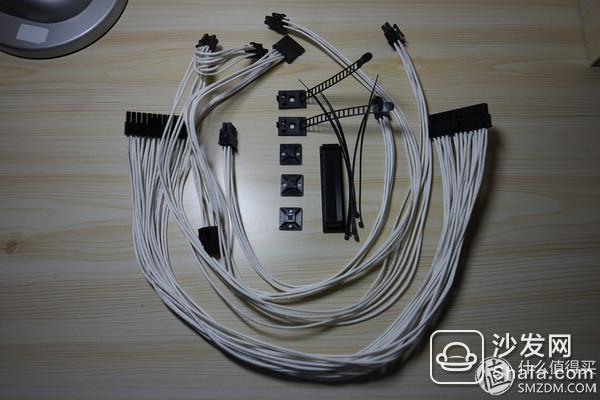
In the first part of this series, I briefly introduced some of the preliminary preparations that are needed for no soul alignment, including the selection of power supply and the purchase of custom lines. I also briefly introduced how to save the half of your hands. Die or non-mode power supply
Then in the second article, I’m going to start to introduce my own thinking and practical tutorials.
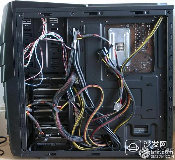
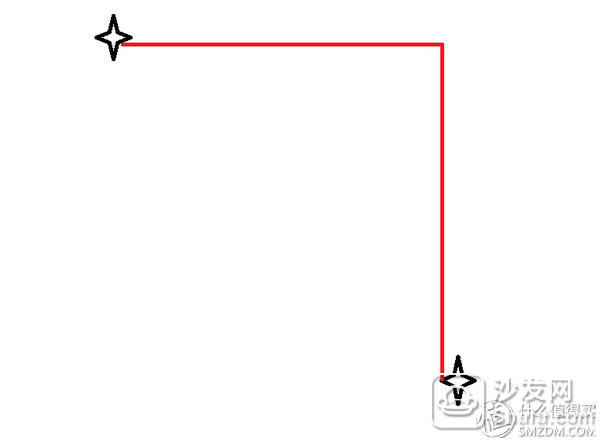
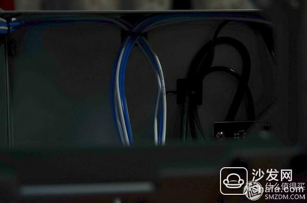
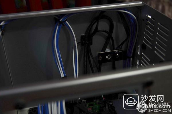
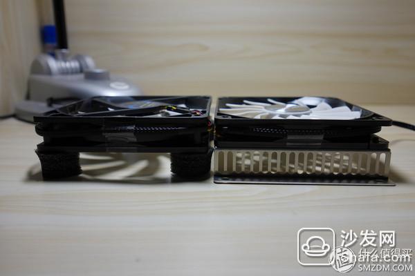
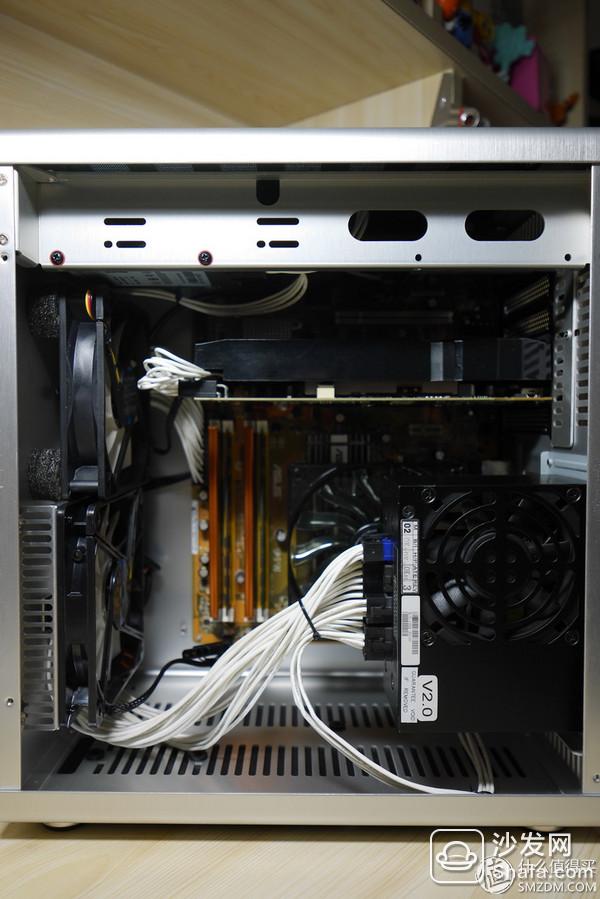
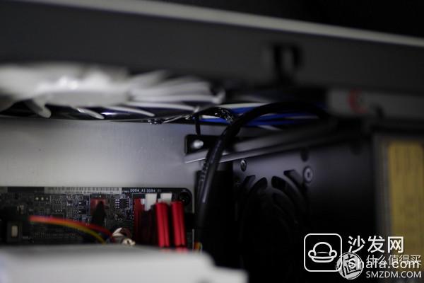
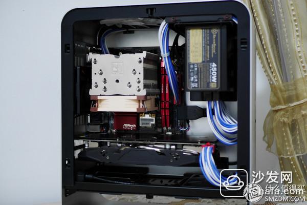
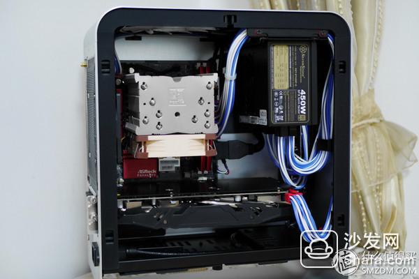
The first thing to say, of course, is the overall idea of ​​routing, that is, how to plan the power line. The two alignment charts in the first picture above are believed to be very intuitive, and the soul line can only get this effect.
And such an expression

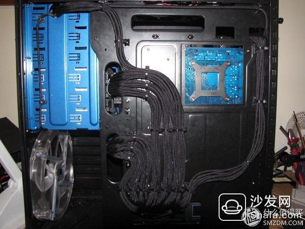
But if you plan the line well, you can do it.
And such an expression

So what is the reason for determining the effect of the alignment, what I personally think is mainly the way of planning the wire line. Although this issue is actually very subjective, I still share my understanding with you.
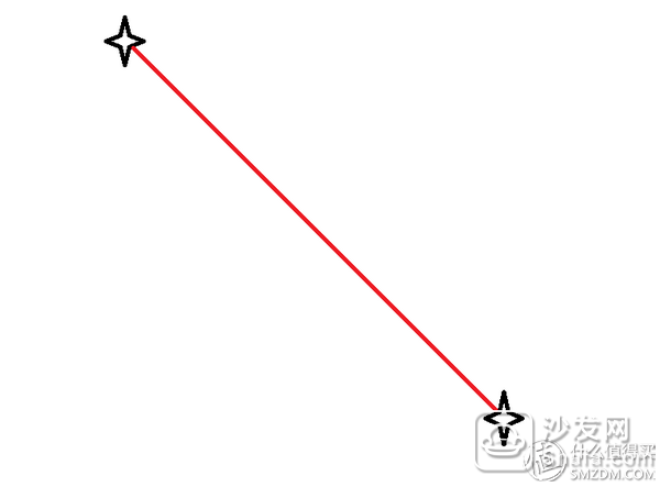
The idea of ​​the soul alignment is actually very simple. Just connect the wire between the two points. If you take a little heart, it may be a straight line.
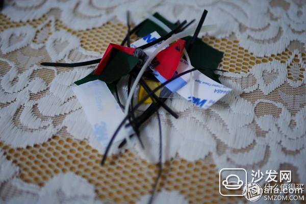
If you don’t care, you’ll walk into a honey stalk
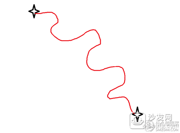
If only one line goes like this, it may be nothing, but as many lines are moving in this way, they will become entangled together to form the soul line in the first picture. In fact, when you look closely at the first picture, you still use a cable to bring a fixed cable, but in the end it's gone like this ghost. The basic reason is that the line is almost zero.
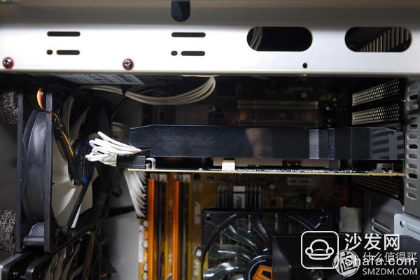
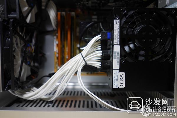
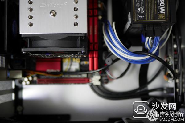
With reference to the second pleasing trace, we can find that when we route the cable, we try to put the cable into a straight line that is perpendicular or parallel to the frame of the chassis, and then put the cables close together and use the figure to illustrate. The cable between two points try to go into the following three forms
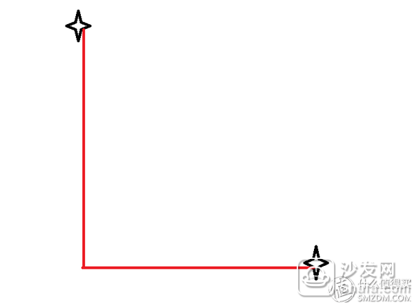
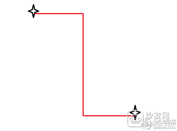
Then all the cables are processed on similar lines and they are finally put together. In this way, even if there are many cables, you can get out of the second picture and enjoy the same pleasing effect.
In addition to the planning of the wire path, there is also a very important big policy is to hide all invisible lines as far as possible, after all, the eyes do not see the mind is not annoying, go back to the mainstream is also the actual direction of this principle reflect
The general direction of the whole is like this, the specific details of the processing or the following combination of different examples of different chassis to explain it
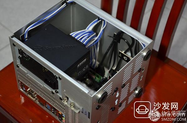
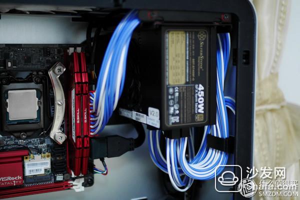
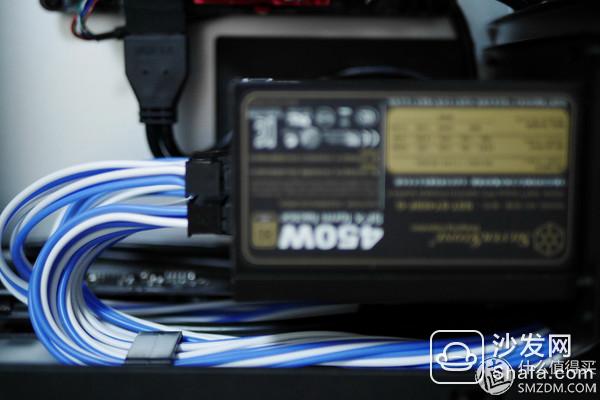
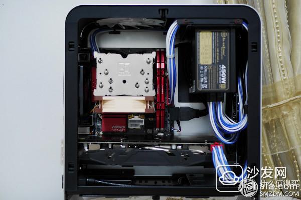
In fact, after the back line and the power supply became the mainstream design of the chassis, the difficulty of the alignment of the ATX and MATX chassis has been greatly reduced. Because of the larger board type, the space inside the chassis is also very abundant, and various back lines The processing of small details such as holes and wire ties is becoming more and more perfect, and even ordinary non-mode power supplies can do well
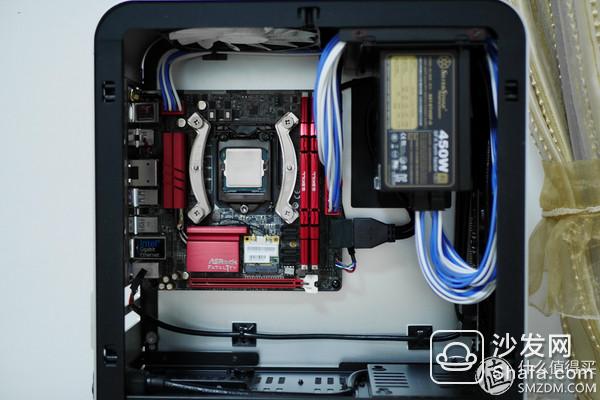
For example, I previously used a machine equipped with a Delta NX350. After the back line, the wire on the front of the machine is quite concise, and the bottom baffle also blocks the power supply and most of the wires.
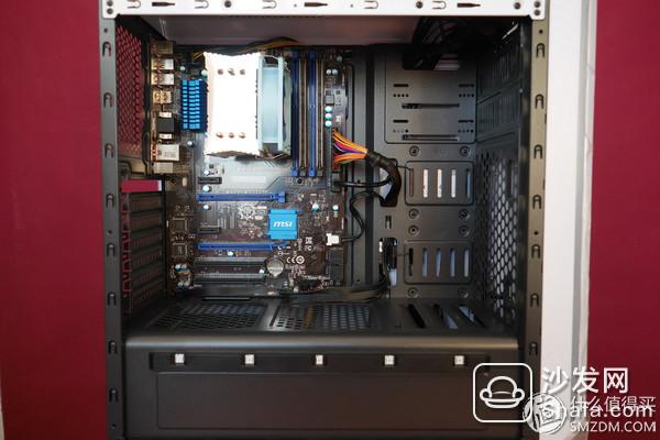
In terms of the back line, I basically go in a straight line or a right-angled form. However, the original line of non-mode power supply that is hard and black can be regarded as such is basically my limit.
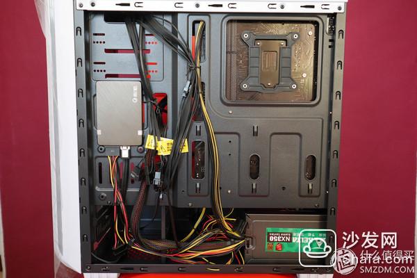
Therefore, everyone can see that it is not difficult to set the alignment in the front-line chassis under the current power supply. As long as the back-line hole in the corresponding position is used, there can be almost no exposed bare cables. Still have to be tied together to tie the larger bundles of wire together, and then go straight. For the chassis with sufficient cabling space, the biggest difficulty in cabling is no longer the power cable, but the connection between the motherboard and the chassis, you can see me from the first one. Still sticking to the edge of the motherboard and chassis, try to make it as inconspicuous
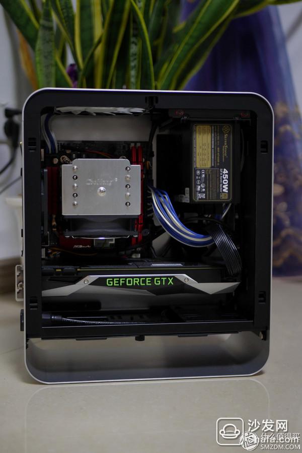
Since the ATX and MATX chassis are able to walk the back line and have enough internal space and there is no great difficulty in routing, I will use the case of several unfavorable ITX boxes to explain this extreme situation to everyone. How to deal with
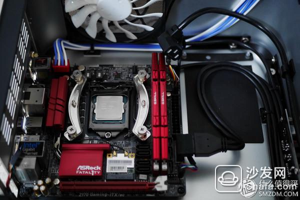
ITX small box is difficult to trace because of limited internal space, coupled with a domestic frustrated chassis manufacturers and extremely like to produce ITX aluminum chassis can not go back line, so I really like the exquisite feeling of aluminum ITX small box I really I can't say anything wrong. I'm talking about you.
It is necessary to explain that one of the first batch of ITX products launched by Rexroth was V3+. At that time, the chassis structure of Tsubaki was almost entirely based on the splicing force, but the internal workmanship was still at a disastrous level. Even the best machine is now installed. It's better to wear gloves. If you don't wear it, you will surely have a lot of honeysuckle like me.
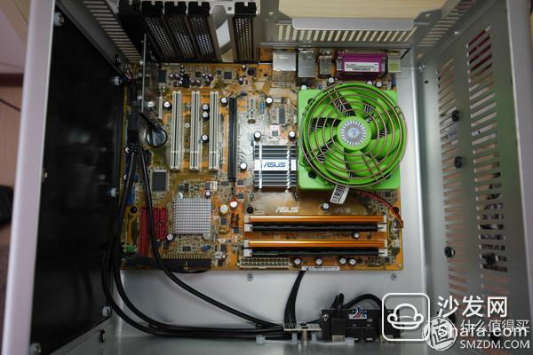
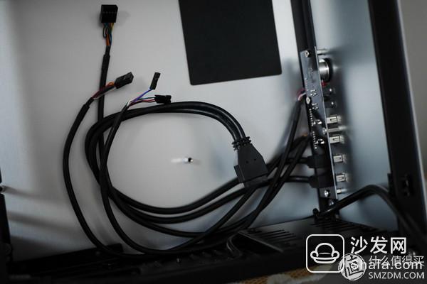
This chassis is still on sale, considering its very low price is a good choice for getting started with an ITX aluminum box. Because of the existence of the hole flow side plate, the heat dissipation effect can still be achieved, and there is also a front USB2.0, the specification is still not outdated. However, if you don’t take the slightest thought on the line, it’s easy to become like this:
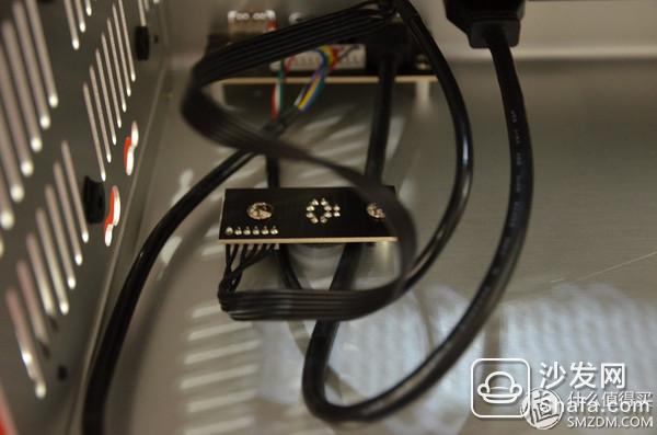
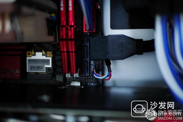
In particular, the IO area on the motherboard is simply a hard-hit area: the hard disk line, the front USB cable, and the motherboard 24pin cable all huddled together.
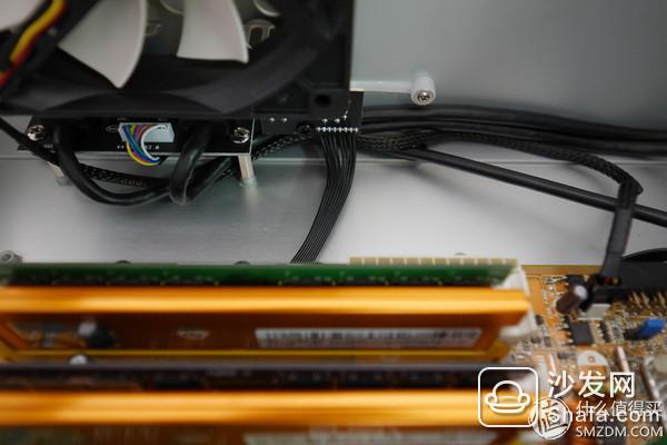
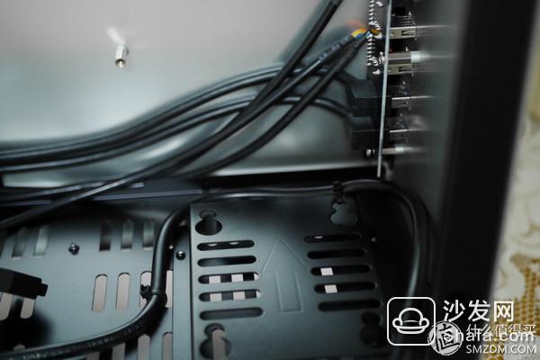
Rehabilitating this hard-hit area certainly has to come slowly. First of all, we must take the wire that can take the top line and go backwards. Maybe you will ask how to move the box back line. In fact, Si Bo's ITX box basically has a certain back line capacity, because the copper column fixing the motherboard screws is designed to be higher, then this section is propped up by copper pillars. Board space is where we go. Here I'm going back the line from the bottom of the motherboard to the SATA data cable of the hard disk.
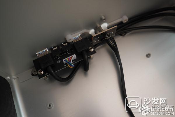
Then we must start to do the finishing of the IO interface of the front of the wire, which is a necessary part of the reeling Bo shell chassis line. Personally, it is recommended to remove the entire front panel and decide on the proper cabling method. For example, here I am using the front panel fixed copper column to sort out the two lines of the front USB interface
The processed IO area is already stronger than before and basically fits the chassis
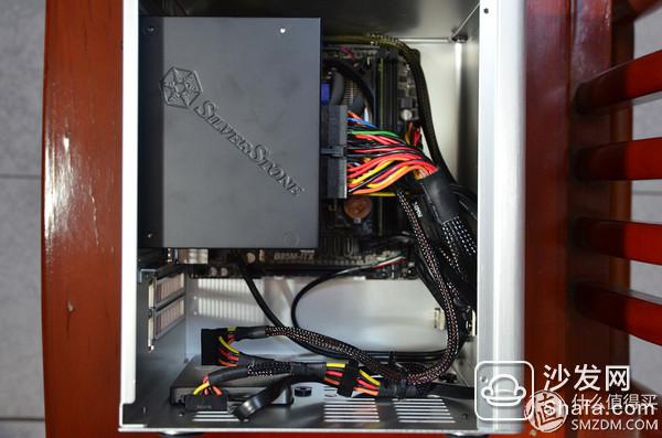
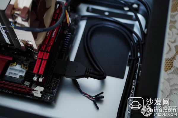
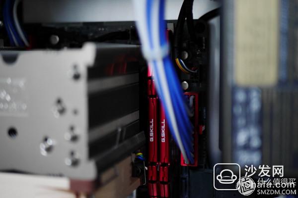
Then we began to walk the power line with the help of the custom silicone wire. The first is the CPU4pin wire. Taking into account the position of the power supply did not go from below the motherboard, but chose to follow the edge of the chassis to follow the straight line and right angles.
The power cable of the hard disk at the bottom of the chassis is also treated as such: straight and right-angle wires along the edge of the chassis
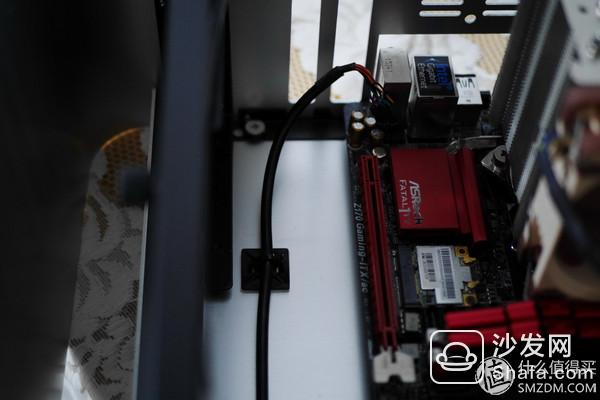
Then two lines in front of the power supply turn
By the way, you can see the processing of the next IO wire
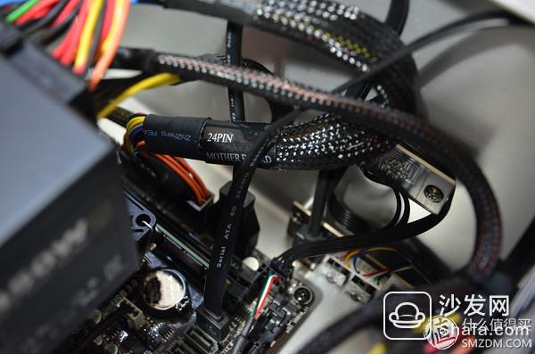
Because the main board 24pin is not far from the power supply, the direct connection does not perform special routing.
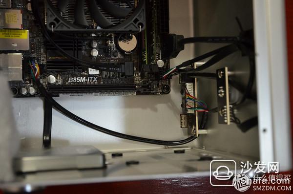
From other angles, you can see that the alignment is still a lot stronger than the initial one. Basically all the wires fit the edges of the chassis, and the overall layout will not affect the main body of the machine.
Through this example, we should be able to see that when dealing with this kind of ITX small box that can't go backwards, the most important thing is not to panic, find some cables that can be processed through the back line, and straighten out the various types of front panel. Cables, then methodically arranged according to the edge of the chassis to arrange the power cords. As long as you follow this general direction, the final product will not be too much of the soul. Of course, custom silicone line can help reduce the difficulty of alignment.
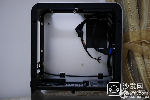
Not only is the ITX small box unable to go back the line will be a headache, can not go back line of the ATX chassis will also make people walk the line is very hot, for example, is also the current minimum production ATX chassis launched by Rexroth - RM2
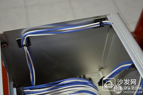
Because the same no-line design and space is limited, the first step is similar to the V3+. It is to find the individual cables that can be used for the back line and the wires that handle the front panel.
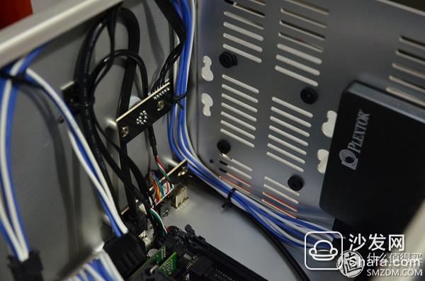
First of all, we still remove the front panel, and then use fixed copper posts to fix the two hard and black wires on the front USB3.0, and then put the panel back to get stuck on the two wires.
The audio cable and the usb cable cannot travel backward because of the length, but the switch cable can be hidden under the main board. After the overall processing is still relatively simple, acceptable
Incidentally, it can help hold the power cable of the front chassis fan
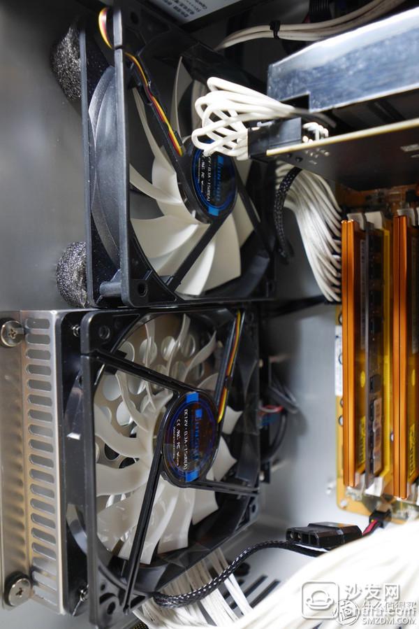
Unlike the V3+, the RM2 has its own front-chassis fan, and I bought one myself, so it is two. First of all, there is space created by the bracket under the two fans.
So still combine the silicone custom line to prepare to use this space
First, fix the power lines of the motherboard, graphics card, and hard disk to the front panel
Then install the fan cover
After the possession of the line, although the power line is still not a good way, but the whole has been refreshed
The upper part of the video card and hard disk and other parts of the wire are basically hidden
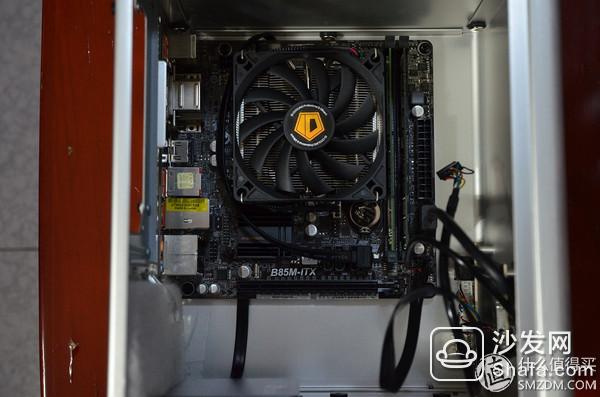
Below here is take a good CPU4pin line
Through this example, we can see that for Tsubaki's series of no-line-designed Trap Boxes, the initial processing methods are actually similar. It is nothing more than looking for the wire that can take the back line, and then the front panel. The lines are rearranged more neatly and more side by side. Another is to use the design of the chassis itself to carry out some hidden line work, so that the final line of finished products can be more concise
In fact, these two machines were not tormented for long, and it took me a long time to leave. So the route plan now looks like there are many things that can be improved. However, the following UMX1 plus is always with me about the chassis, but also gradually improve this route program
In the beginning, the front USB 3.0 and switch cables were used together to bypass the bottom right of the motherboard copper pillars for back-line processing.
Then the CPU8pin wire bypasses the power supply
Finally, the motherboard 24pin directly connected to the power supply, just stuck to fix the front audio cable. At the same time the graphics card 8pin line from the front of the USB3.0 line below, just can be suppressed
The overall result of the final alignment is this, although generally still okay, but there are still many cables are in the flying line state, and the graphics card line is still a temporary use of the original line is not customized, resulting in uneven color tone
This is also why the last one I started buying the line was to make a separate card line. Of course, I was finally determined to feel like I was doing it again. Since the entire line was redone, the route plan naturally starts from scratch.
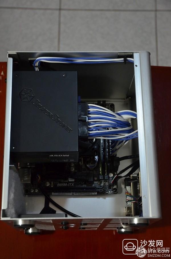
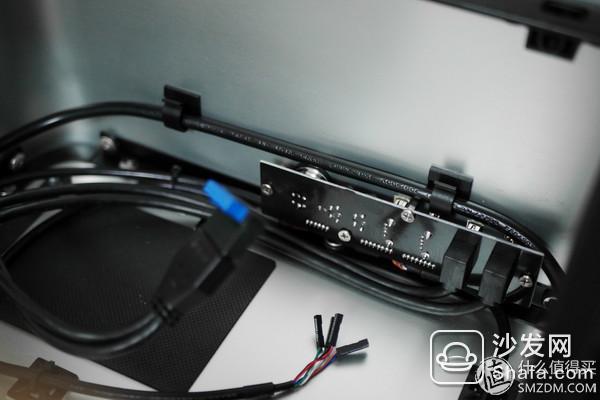
First of all remove all the components, the structure of this chassis is actually very simple, but the means of possession of the line is somewhat special, to use the route near the fan above the power supply
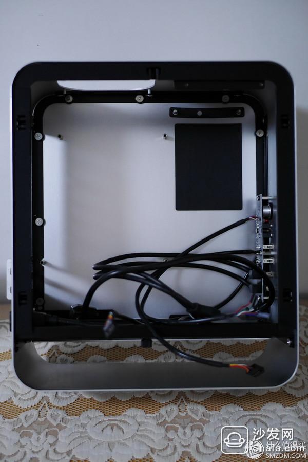
You can see UMX1 this box first still have to solve the line of this bunch of front panel. The perfect way is to customize the front panel into a silver-plated wire, but even if it is not, it can be handled more perfectly.
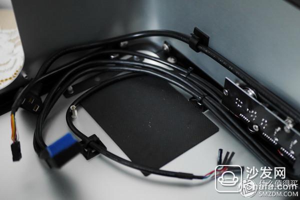
The first step is to fix the power extension cable, use the hard disk bracket on this side, and then use the cable tie to get it.
Then put the main board into the fake group and test the length and approximate placement of each cable. Here you can see the role of the pre-USB 3.0 artifacts mentioned in the previous section
The length of the front audio line is also exactly
Then the layout of the front panel is roughly shaped: the audio cable goes from below the graphics card to a straight line, and the other cables are basically taken from the power supply.
First take the USB2.0, 3.0 and switch cables along the edge of the chassis, and attach the cable manager to the cable tie. You can see that the power extension cable has also been fixed along the straight line.
Then, the USB2.0 cable completely bypasses the power supply, the switch cable bypasses the upper right corner of the motherboard fixed copper post, and the USB 3.0 cable is only bent and is placed near the power supply position and is directly pressed by the power supply.
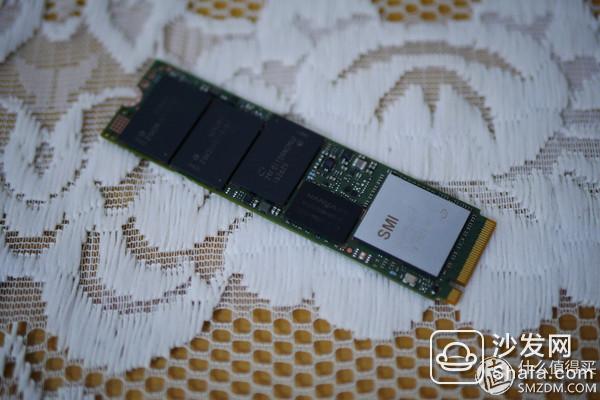
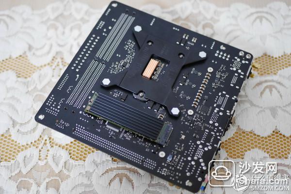
Then we deal with the cooling of M2 interface SSD
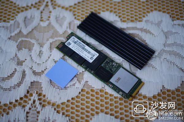
First tear off the SSD sticker to avoid affecting heat dissipation
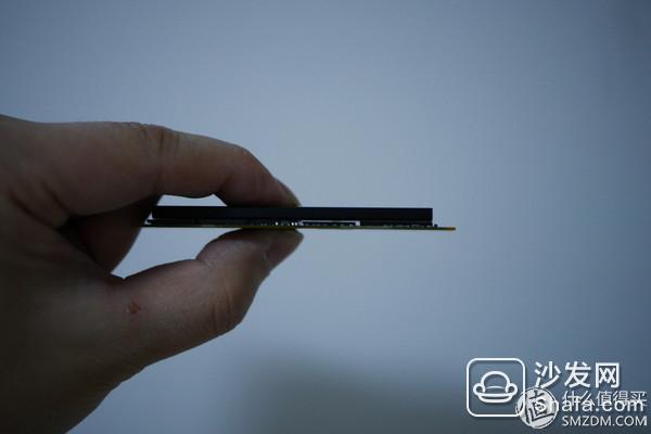
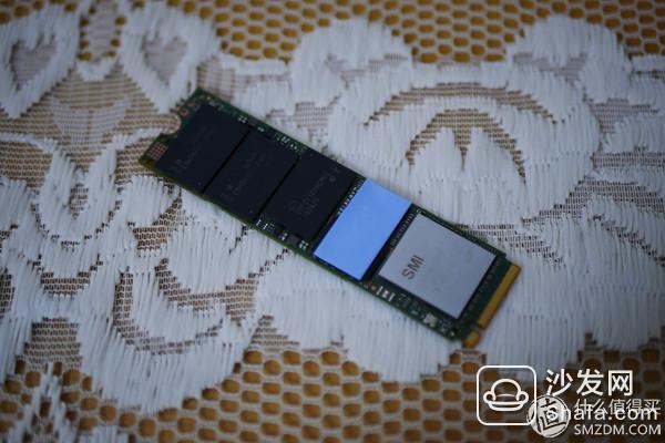
Put the heat sink on it and see if there is a gap between the cache and the heat sink
So put some thermal pad
Remove the 3m adhesive on the back of the heat sink
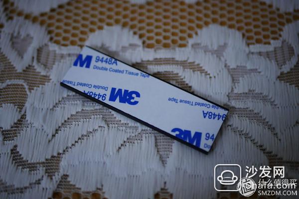
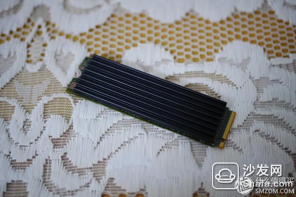
After blackening regardless of the cooling effect, bigger's tip is huge
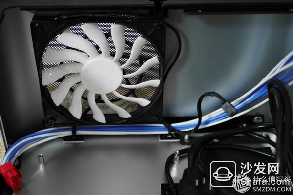
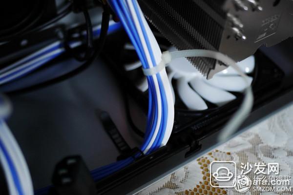
Then we start to take the CPU8pin line, similar to the front panel, or along the edge of the chassis through the cable tie to fix it. Note that it is necessary to remove the upper fan before proceeding smoothly
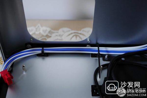
After installing the fan, plug the fan's power cord into the right tie that is not stretched on the top and fasten it together.
Once again, put the motherboard in the fake group and check if the length of each wire is appropriate.
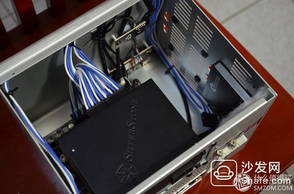
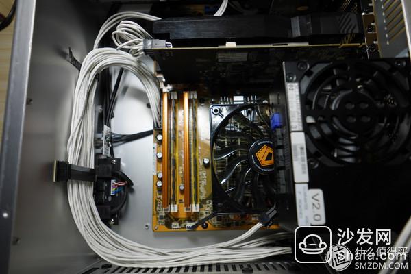
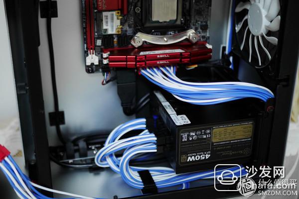
The power supply and the motherboard 24pin line are also installed to see the effect, the initial effect has come out
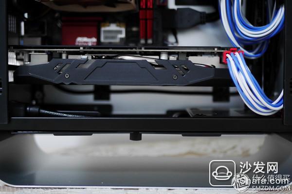
The graphics card is also installed, I believe we can already see the difference with the previous line program: the cable is relatively closer to the front panel of the chassis, the space below the power supply and the motherboard IO area becomes wider and more organized
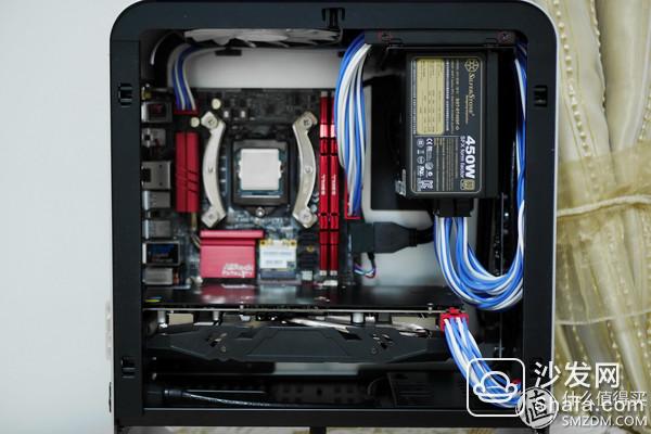
And you can see this move, the motherboard 24pin line will not be basically blocked the cooling fan power supply

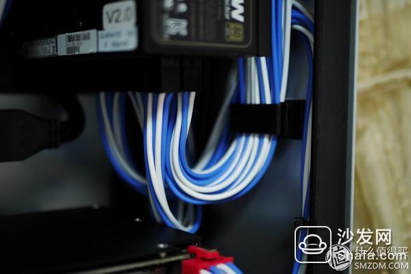
However, the cable between the power supply and the front panel of the chassis is still very messy and needs further processing.
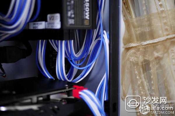
My approach is to stick a cable manager and then let the cables constrain each other
It can be seen that the space around the power supply is still sufficient and it will not have much impact on the heat dissipation.
The overall power supply area can still be handled, but I feel that this kind of space-constrained chassis or silver plated wire will be a little better, it will not appear so bloated
After all the fake groups are finished, the last details can be polished. Firstly, the 24pin on the motherboard is fixed. In addition to using a white tie to avoid damaging the color matching effect, a wire loop is installed to better wind the power supply from above. Over
The fan power cable at the rear of the chassis is also secured with black tape

After all the cable management is completed, you can see from the right, most of the cables are hidden by the front panel, achieving a very good cable management effect.
Even from the left and the front, the effect is acceptable
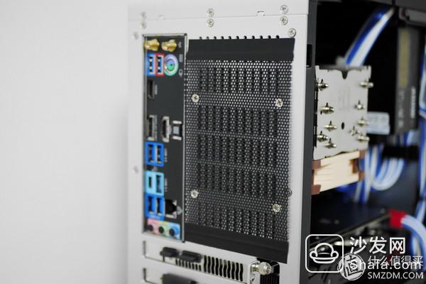
In addition, a layer of dust-proof net was fixed on the back of the chassis with black tape. This look is indeed better than the box of black silk.
Now take a look at the details of the cabling in each corner of the chassis. The first is that the CPU8pin is almost completely blocked by the box top fan, hiding the line effect is quite good

Front USB3.0 and switch wiring processing effect is also good
Motherboard 24pin and front USB2.0 interface
Power interface
The video card and the front audio cable below
Also reserved a video card 6pin, to deal with 8+6pin power supply graphics card is no pressure

However, there are a lot of cable managers and ties, as well as the time and effort behind the good results. The value of these things is not worth it. It really is that there are one thousand people in the heart of Hamlet.
Judging from the above examples, there are basically no alignments for traces. Different sizes of chassis, power supplies of different specifications, and traces of different ideas all affect the final trace effect.
And after all, unlike the other accessories, you can experience intuitive performance gains by spending more money. The route itself does not have any substantial improvement in the performance of the computer. So why should the cables in the chassis be neatly arranged? Perhaps it is because of the deep love for the machine and the heart to shake it.
The Dasoft, which started to look at in 1998, is now in its final phase. But as long as the enthusiasm of the heart is still there, I'll probably go down this road.
This small series is over here, we will do goodbye the next time, diarrhea
We've been around for over 15 years. We make sure our sound is The Best Sound.
Our products include gaming headset, Bluetooth Earphone, Headphones Noise Cancelling, Best Wireless Earbuds, Bluetooth Mask, Headphones For Sleeping, Headphones in Headband, Bluetooth Beanie Hat, bluetooth for motorcycle helmet, etc
Manufacturing high-quality products for customers according to international standards, such as CE ROHS FCC REACH UL SGS BQB etc.
We help 200+ customers create custom Bluetooth headphones, earbuds, earphones, etc audio products design for various industries.
Bluetooth Headphones,Noise Cancelling Headphones,Bluetooth Earphones,Best Headphones
TOPNOTCH INTERNATIONAL GROUP LIMITED , https://www.mic11.com