1 Introduction
With the development of variable frequency speed control technology and people's improvement of the quality of domestic water, the variable frequency constant pressure water supply system has replaced the traditional water supply system and has been widely used in residential water systems. At present, most domestic enterprises still use the traditional constant pressure pump to switch the pressurized water supply mode, the water pressure is unstable, and energy is wasted. Therefore, the constant pressure water supply system with high reliability, high price and good control performance has high practical value. Compared with the past water tower or high water tank and pneumatic water supply method, the variable frequency constant pressure water supply method has incomparable advantages in terms of equipment investment, economical operation, system stability, reliability, and automation degree. It has energy saving effect. At present, the variable frequency constant pressure water supply system is developing in the direction of high reliability, full digital microcomputer control and multi-variety serialization. This paper uses PLC and frequency converter to realize the design of constant pressure water supply control system. The water pressure fluctuation is small and the operation is stable. It is an advanced and reasonable energy-saving water supply system.
2. The structure and principle of variable frequency speed regulation constant pressure water supply system
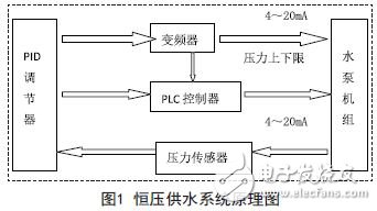
The system uses two pumps for water supply, FRENIC5000 G11S frequency converter is selected, PLC selects Omron small PLC, frequency conversion speed control is the core of constant pressure water supply system, the system is controlled by the frequency converter to directly pressurize or depressurize water to the pipe network outlet. According to the measured pressure at the outlet of the pipe network, the pressure signal is sent to the PID regulator by the pressure sensor. The PID regulator adjusts the pressure according to the deviation between the pressure set value and the actual pressure value, and outputs the frequency given signal. IRF (4~20mA) is given to the inverter. The inverter controls the speed of the pump according to the frequency reference signal IRF, and sets the upper and lower limits of the pressure on the PID regulator. The PID sends this signal to the PLC controller to realize two sets. Switching between power frequency and frequency conversion between pumps. The schematic diagram of the system is shown in Figure 1.
3. Constant pressure water supply system design
3.1 main circuit design
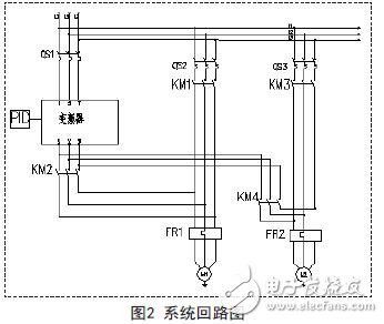
The system adopts two control modes: manual and automatic. The PLC firstly starts the frequency conversion of the main water pump. The pressure sensor feeds the pressure of the main pipe to the PLC, compares it with the preset pressure, and adjusts the output frequency of the inverter through PID calculation. Maintain a constant water pressure. If the water consumption is as large as 1 pump can not reach the given pressure at full speed, the PLC will input the pump from the frequency conversion operation to the power frequency operation, and at the same time put another water pump into the frequency conversion operation, increase the water supply volume of the pipe network to ensure the pressure. stable. When the water consumption is reduced, the PLC first stops the pump running at the power frequency to reduce the water supply. The whole system ensures that only one pump is converted to constant pressure water supply during the frequency conversion operation. The system adopts the variable-frequency pump circulation mode, and the pump is turned off in the order of “first open and close firstâ€, which not only ensures that the system has a backup pump, but also effectively prevents the standby pump from being “embroidered†for a long time. The main circuit diagram of the system is shown in Figure 2.
3.2 Control circuit design
The control circuit is shown in Figure 3 below. The SB1 control system is started, the SB2 control system is stopped, and when the pump is overloaded, the A5 light is on. When the inverter fails, the A6 light is on. A1 and A2 are the frequency conversion and power frequency operation indicators of pump 1, respectively. A3 and A4 are the frequency conversion and power frequency operation indicator of pump 2.
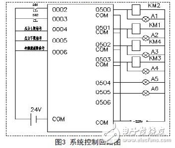
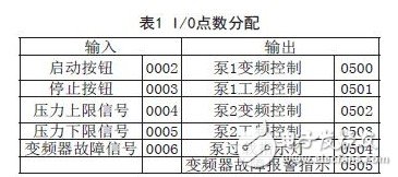
The I/O points of the PLC controller are allocated as shown in Table 1.
4.PLC control flow chart design
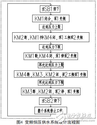
According to the constant pressure water supply operation requirements, the PLC control system should monitor the tap water and the water supply port at any time to decide whether to start the water pump. The main task of the PLC control program design is to receive the input of various external switch signals and judge the current water supply status. The output signal controls the operation of the relay, contactor, etc. to adjust the operation of the pump. PLC and frequency converter are the core part of the system. The key to stable operation of the system depends on the rationality and feasibility of the PLC program and the setting of the inverter parameters. The system adopts manual or automatic working mode. After the system is started, the pump 1 first enters the frequency conversion operation. When the pressure upper limit signal is detected, the variable frequency pump is switched to the power frequency, and another pump is started to operate in frequency conversion. When the pressure is detected, when the pressure is detected. When the lower limit signal is used, the power frequency pump is cut off and only becomes the variable frequency pump. The flow chart of the system design program is shown in Figure 4.
5 Conclusion
This program consists of OMRON C series small PLC controller combined with Fuji FRENIC 5000G11S series inverter and pressure sensor constant pressure water supply system to achieve the purpose of constant pressure water supply, to achieve a true unattended shut-off, cycle switching pump. Since the frequency converter has a soft start function, the impact of starting a large current on the power grid is eliminated, thereby prolonging the service life of the pump. The actual operation proves that the system has the characteristics of high reliability, high degree of automation, easy maintenance and high energy saving. It has great application value and can be widely used in industrial water supply, domestic water supply, fire water supply, central heating and other water supply. system.
Cable Management refers to an important step during the installation of building services (i.e. electrical services) and the subsequent installation of equipment providing means to tidily secure electrical, data, and other cables.
Our factory has already kept over 20 types Cable Management Frame in our catalogue for your selection. Mainly Cable Ring Manager for 19" size also offer 10" with 3 rings. You can choose Horizontal Wire Management Panel or vertical wire management panel in 1U and 2U.For different function, you can refer to with cover or not even with brush or not.

Cable management frame also called cable organizer or Cable Organizer, it is easy to install or uninstall. You can change the quantity and location as you like. It makes your network cables orderly, easy and effective.
19 Inch Cable Management Frame
Network Cable Management, Computer Cable Management, Rack Cable Management
NINGBO YULIANG TELECOM MUNICATIONS EQUIPMENT CO.,LTD. , https://www.yltelecom.com