1 Introduction
In the large-scale enterprise automation system, Ethernet and PC are used in the upper-level enterprise management layer and production monitoring layer, and fieldbus is used in the lower-floor workshop, such as RS-485, CAN, lonWorks, etc. The two-layer communication is usually realized by an industrial control machine plus an Ethernet card plus an interface card corresponding to the field bus on the PC slot or an EPP interface card of the parallel print port. This connection method is costly and has a long development cycle. The interface card becomes the communication bottleneck of the upper and lower layers of the system. Once the fault occurs, the connection between the upper and lower layers will be interrupted; for this reason, the inexpensive MCU-based Ethernet-CAN bridge replaces the expensive industrial computer plus interface card to realize Ethernet and CAN. The direct connection of the bus network is of great significance.
2. System design
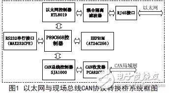
Because there are Ethernet network and CAN bus data processing in the system, it is necessary to use large-capacity RAM for temporary storage network data. The P89C668 high-speed Controller integrated with 8KRAM and 64K Flash is used. As shown in Figure 1, the system uses chip RTL8019. Network data transmission and reception, using the chip SJA1000 to process CAN bus data, and at the same time to facilitate the conversion of the conversion bridge system and parameter settings (CANID, CAN baud rate, Ethernet physical address, IP address, gateway address, subnet mask) and save To increase the range of system use and flexibility of use, the system also expands the serial communication RS232 interface and 24C256 serial port storage circuit.
3. System hardware design
3.1 Ethernet interface circuit design
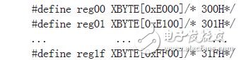
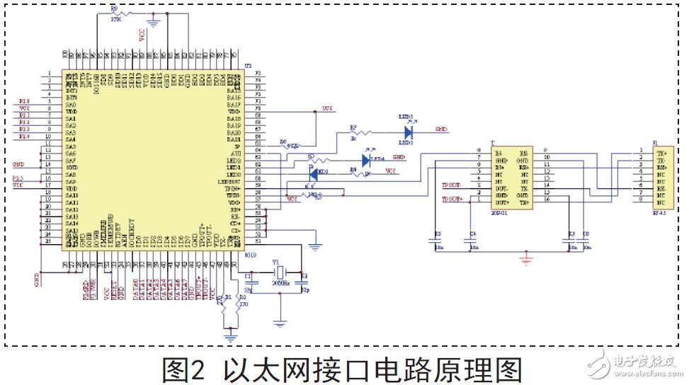
The Ethernet interface circuit is shown in Figure 2. The 36-to-43 pins in the circuit are directly connected to the P0 port of the MCU. RTL8019AS has three output pins that reflect their working status, respectively LED0, LED1, LED2, respectively output network connectivity, data transmission and data output status; IOCS16 is a 16-bit or 8-bit I/O selection pin, when powered When reset, when the pin is low, the network card will select 8-bit mode. When it is high, the network controller will select the 16-bit mode. The circuit uses a resistor R9 (27K) to pull down. It is low, so the network card selects 8-bit mode. Since each pin of RTL8019AS (except AEN) has a 100K pull-down resistor inside, the internal detection is low when each pin is floating. Figure 2 shows that 85, 84, 82, and 81 pins respectively. Suspended, thus selecting the base address 300H, so the circuit expansion should be configured as a reference, RTL8019AS address line A19~A10 is fixed to ground, A9, A8 is connected to P2.5 as the address selection end has a single-chip control instead of 34-pin AEN (direct grounding) is used as the address selection to disconnect, A7, A6, A5 are fixedly grounded, and A4~A0 should be different according to the address of the RTL8019AS register to be accessed, so that P2.0~P2.4 from P89C668 Select RTL8019300H~31FH, so the corresponding P2 port address line change range is 0xE0-0xFF, because only the P2 port is used to select the address, and the P0 port does not participate in the address addressing circuit. The addressing I/O of the MTL to the RTL8019AS is not continuous. Reg00~Reg1F are defined in the program to correspond to the 300H~31FH ports respectively, as defined below:
3.2 CAN bus interface circuit design
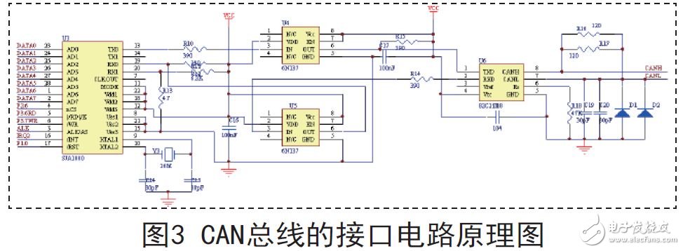
As shown in Figure 3, the CAN bus interface circuit is mainly composed of P89C668 processor, CAN communication controller SJA1000, CAN bus driver 82C250, high-speed optocoupler 6 N 1 3 7 circuit, microprocessor P 8 9 C 6 6 8 Responsible for SJA1000 initialization, control data acquisition and transmission by SJA1000; in order to enhance the anti-jamming capability of CAN summary point, TX0 and RX0 of SJA1000 are connected with 82C250 through high-speed optocoupler 6N137, which realizes the node on CAN bus. The electrical isolation improves the stability and safety of the hardware of the system; the resistance of the CANC and CANL pins of the 82C250 is connected in series with 60 ohms (two 120 ohm resistors in parallel) to eliminate the reflection of signals in the circuit. Two 30pF small capacitors are connected in parallel between CANH and CANL and ground to filter high frequency interference and certain electromagnetic radiation on the bus. A lightning protection is connected between the two CAN bus inputs and the ground. Tube, when there is transient interference between the input terminals and the ground, the discharge through the lightning protection tube plays a certain protective role, and R18 is the slope resistance.
Experts keep working hard and provide this Garden Light in the market in proper safe packing. These lights are made of damage free parts.
Backed by a team of knowledgeable professionals, we are an identified firm in the market for providing an extensive range of Garden Light.
Keeping in mind the requirements of customers, we are engrossed in providing Garden Lights. These lights are developed with the help of modern machinery and technology to ensure no scope for defects.
Garden Light,Solar Led Garden Light,Solar Lawn Garden Light,Decorative Garden Light
Delight Eco Energy Supplies Co., Ltd. , https://www.cndelight.com