1 Introduction
The semiconductor light-emitting diode (LED) light source has the characteristics of small volume, high efficiency, fast response, easy dimming, wide color gamut, no mercury pollution, long service life, etc. It is a new energy source with energy saving and environmental protection. With the continuous improvement of LED technology, especially the continuous improvement of light efficiency, it has broad application prospects in the fields of projection display, backlight source and urban lighting. However, since the spatial intensity of the LED is similar to the Lambertian type distribution, the illuminance formed on the illuminated surface is rapidly attenuated with the increase of the exit angle, and it is difficult to meet the long-distance illumination such as the signal projection lamp for the flashlight, port or dock. In actual need, in order to make the beam parallel to improve the utilization of light energy, optical designers try to design reflectors, refractors or eclipses in various ways to improve the layout of the light on the target surface to meet the needs of the actual situation.
At present, LED secondary optical design mainly has two methods: direct experience method and solution equation method. The direct empirical method mainly draws the structure of the optical component through CAE three-dimensional mechanical modeling software, and introduces the structure into optical simulation software such as Tracepro, and gives some optical properties to the structure, and finally passes Monte Carlo non-sequential light. Trace to determine the illumination distribution on the illumination surface and the light intensity distribution of the entire system. Because of the arbitrariness of this design, the designer often needs to modify the structure of the optical component several times, and simulate it multiple times to complete the design. Such a method does not require much theoretical calculation, and the key to the design often depends on the designer. Personal experience. The equation solving method constructs a system of equations based on the illuminating properties of the light source and the illumination requirements that need to be achieved. The unknown number is the coordinates of the points on the free surface to be solved. After the initial conditions are given, the analytical solution or numerical value of the equations is solved. Solution, you can get the surface data of the free-form surface and achieve the required lighting requirements. This method eliminates the time required for trial and error and improves the design efficiency, but it has higher requirements for the designer's optical construction ability and mathematical foundation.
In this paper, based on the characteristics of LED light source and the intensity distribution of the target surface, a simpler free-form refractor is designed according to the requirements of Snell's law and optical expansion in non-imaging optics. Uniform illumination over long distances.
2 Design principles
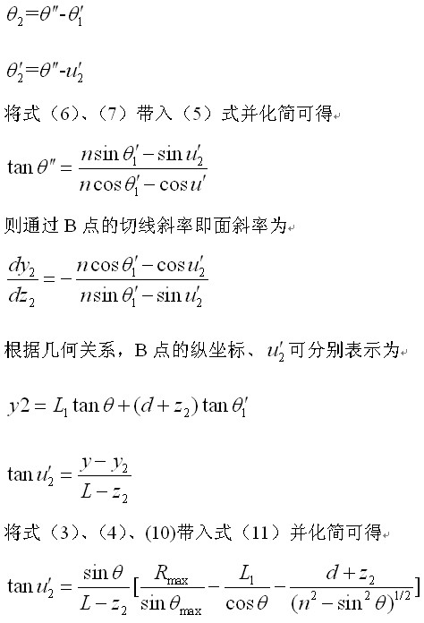
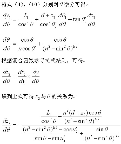
Establish a coordinate system as shown in Figure 1. Let the LED light source be at the origin of the coordinate system, the front surface of the lens is a plane, and the back surface is a curved surface, which is a free curved surface that needs to be designed. The angle in the figure is the incident angle of any light emitted by the LED light source and the normal line of the front surface of the lens, which is the angle of refraction after the light enters the lens, and the angle of incidence and the angle of exit of the light on the free curved surface, respectively. The last light hits the target surface. In the figure, , is the distance between the surface of the light source and the front surface of the lens, the thickness of the free-form lens, and the distance between the vertex of the free-form surface and the receiving surface. Let the refractive index of air be 1, and the refractive index of the free-form lens is .

Figure 1 Schematic diagram of LED collimating lens analysis model
Fig.1 Scheme of LED collimating lens analysis model
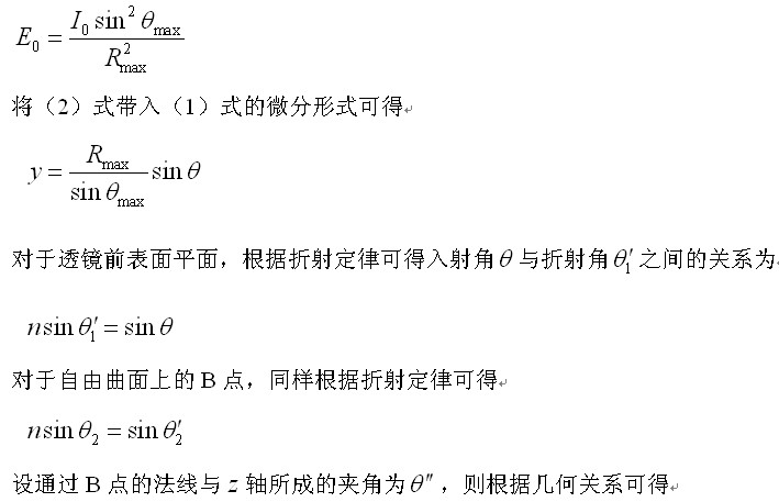
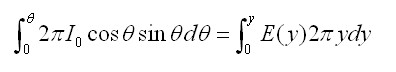
Let the LED chip light source be a Lambertian distribution, the spatial light intensity distribution is, then the axial direction light intensity is, the target light field illumination distribution function is the differential form of the solid angle element. Ideally, the lens has no absorption, no reflection and scattering, and the luminous flux emitted by the solid angle of the light source corresponding to the cone angle is equal to the luminous flux received within the corresponding radius of the target illumination surface, and the energy balance equation is
It is assumed that the purpose of the LED lens design is to require the illumination of each point on the target screen after the light passes through the lens to be a certain value, that is, the illumination of the target illumination surface is uniform. Considering that a certain solid angle of the light must correspond to the area distribution of a certain target illumination surface, when the angle of the light exit is the largest, the position coordinate of the light on the target illumination surface is, and (1) the boundary condition is obtained.